Submersible electromagnetic flow sensor

An electromagnetic flow and sensor technology, which is applied in the direction of detecting fluid flow and volume/mass flow generated by electromagnetic effects, can solve problems such as unreliable structure, high construction cost, and long installation time, and achieve a wide range of applications , low maintenance costs, and low construction costs

Inactive Publication Date: 2011-06-15
昆山市鑫源计测科技有限公司
View PDF4 Cites 1 Cited by
  • Summary
  • Abstract
  • Description
  • Claims
  • Application Information

AI Technical Summary

Problems solved by technology

[0004] In order to solve the problem that the overall sealing structure of the electromagnetic flowmeter in the prior art is unreliable, the measurement accuracy is low, it is easy to be damaged, and it is very troublesome to install on various channels at the same time, the installation time is long, the efficiency is low, and the construction cost is also high.

Method used


Image

  • Submersible electromagnetic flow sensor
  • Submersible electromagnetic flow sensor

Examples


Embodiment Construction

[0012] The present invention will be further described below in conjunction with the accompanying drawings.

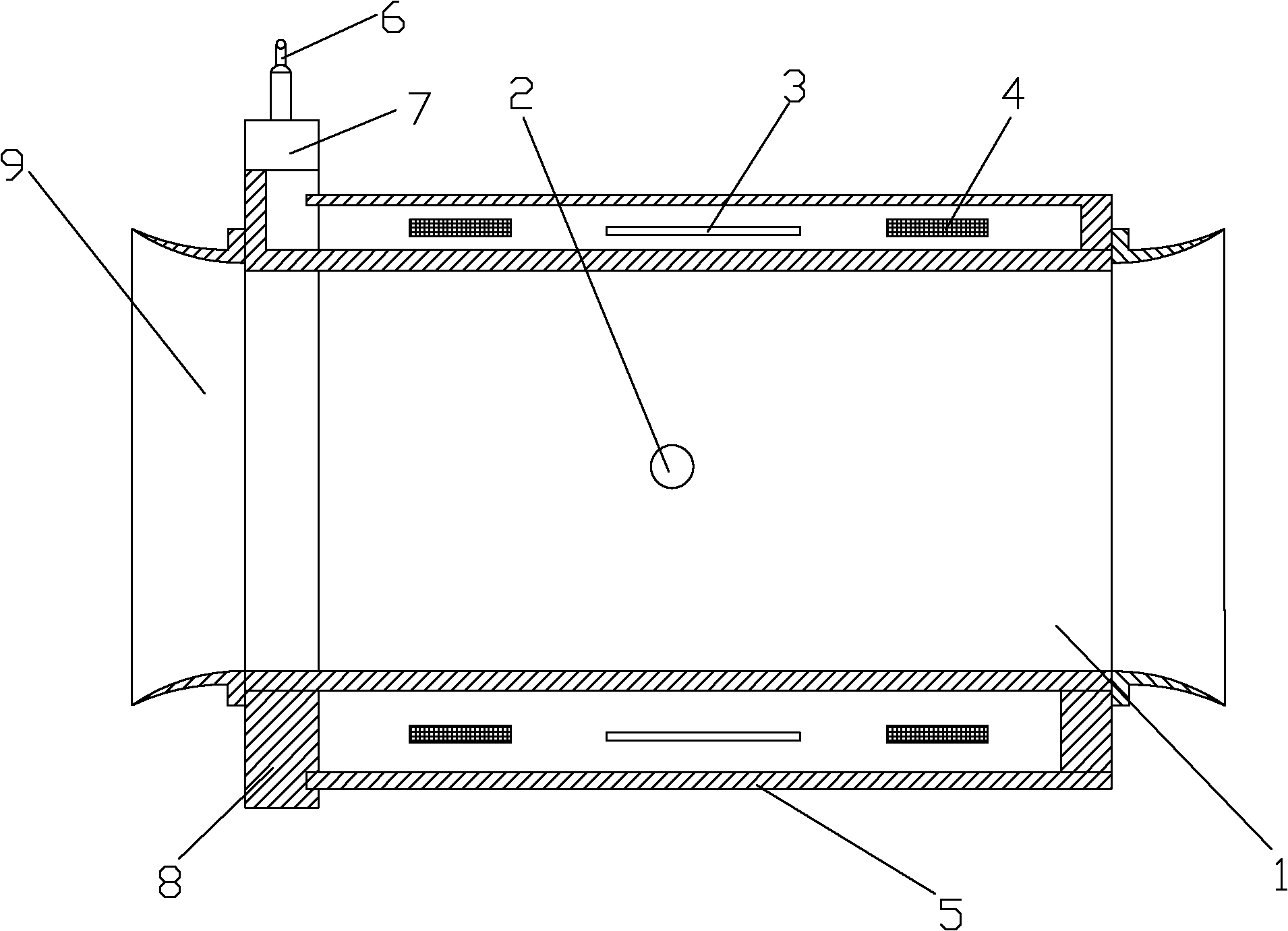
[0013] Such as figure 1 As shown, a submersible electromagnetic flow sensor includes a conduit 1, an electrode 2, a yoke 3, an excitation coil 4, a cable 6 and a housing 5, and a pair of tubes for detecting fluid are arranged on the wall of the conduit 1 at both ends of the central axis of the conduit 1. The electrode 2 of the electromotive force generated by the flow is provided with a circle of yoke 3 on the outside of the electrode 2. On both sides of the yoke 3, an excitation coil 4 for generating a magnetic field perpendicular to the flow direction of the fluid is respectively provided. Between the yoke 3 and the excitation A protective casing 5 is provided outside the coil 4 , a cable 6 for transmitting electromotive force signals is provided on the upper part of the casing 5 , and a cable sealing structure 7 is provided outside the cable 6 for protection. A sid...


PUM


Abstract

The invention discloses a submersible electromagnetic flow sensor, which comprises a guide pipe. The submersible electromagnetic flow sensor is characterized in that the sensor also includes electrodes, a yoke, an excitation coil, a cable and a casing; a pair of electrodes for detecting the electrodynamic potential generated by fluid flowing is arranged on the guide pipe walls on both ends of the center axis of the guide pipe; a circle of the yoke is arranged outside the electrodes; the excitation coil for generating a magnetic field vertical to the fluid flowing direction is respectively arranged on both sides of the yoke; the casing with a protection effect is arranged outside the yoke and the excitation coil; and the cable for transmitting the electrodynamic potential signal is arranged on the upper part of the casing. The submersible electromagnetic flow sensor solves the problems of the electromagnetic flowmeter in the prior art, such as unreliable overall sealing structure, low measurement accuracy, high possibility of damage, complicated installation on various channels, long installation time, low installation efficiency and high construction cost. Therefore, the invention provides the submersible electromagnetic flow sensor with good sealing performance and capability of being installed and used through the simple reformation on the original channel.

Description

[0001] technical field [0002] The invention relates to an electromagnetic flowmeter, in particular to a submersible electromagnetic flow sensor capable of continuously measuring open channels, hidden channels and river channels. Background technique [0003] The working principle of the electromagnetic flowmeter is based on Faraday's law of electromagnetic induction. In the electromagnetic flowmeter, the conductive medium in the measuring tube is equivalent to the conductive metal rod in the Faraday test, and the two electromagnetic coils at the upper and lower ends generate a constant magnetic field. When a conductive medium flows, an induced voltage is generated. Two electrodes inside the pipe measure the induced potential generated. The measuring pipe is electromagnetically isolated from the fluid and the measuring electrode by a non-conductive lining (rubber, Teflon, etc.). However, when the current electromagnetic flowmeter is in use, due to the unreliable sealing ...

Claims


Application Information

Patent Timeline
IPC IPC(8): G01F1/58
Inventor 姜伟明
Owner 昆山市鑫源计测科技有限公司
Why Eureka
Try Eureka