

Bearing buffer unit for motor
A technology of buffer device and bearing device, applied in the direction of electromechanical device, casing/cover/support, electrical components, etc., can solve the problem of increasing the cost of product mounting parts and components, failing to pass the product qualification inspection process, and increasing the noise of bearing running. It can shorten the production cycle, save installation space and product storage space, and eliminate noise and vibration.
Inactive Publication Date: 2011-06-15
胡磊
View PDF3 Cites 4 Cited by
- Summary
- Abstract
- Description
- Claims
- Application Information
AI Technical Summary
Problems solved by technology
The main cause of damage to the bearing is that the high speed of the centrifuge motor causes the bearing to heat up, and the outer ring of the bearing expands outwards. After the motor stops rotating, the motor end cover shrinks faster than the bearing due to the ambient temperature, thereby squeezing Press the outer diameter of the bearing. The outer diameter of the bearing causes the raceway and the balls to squeeze each other and cause damage. After the bearing is damaged, the noise and vibration of the bearing will increase, so that it cannot pass the product qualification inspection process, resulting in the failure of the motor product. The waste is huge; if it is directly used in centrifuges and other supporting equipment without inspection procedures, it will easily lead to safety accidents
In addition, the tail end of the motor shaft protrudes out of the lower end cover of the motor, which increases the installation space required for the product, and the product placement, packaging and transportation also need to increase the cost of more parts and components such as product mounts.
Method used
View moreImage
Smart ImageViewing Examples


Examples
Embodiment Construction
Login to View More PUM
 Abstract
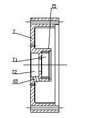
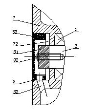
The invention provides a bearing buffer unit for a motor, comprising motor spindles, wherein the motor spindles pass through the centers of a stator core and a rotor core, and are respectively fixed in the upper end cap and the lower end cap of a motor by an upper bearing device and a lower bearing device; the upper bearing device comprises upper end cap bearings which are fixed at the spindles; the upper end cap bearings are arranged in a concave platform of the upper end cap of the motor; the upper end cap bearings in the concave platform are respectively provided with an upper bearing elastic element in a radial direction; each upper bearing elastic element is provided with an upper sealing cover plate in an axial direction; the lower bearing device comprises lower end cap bearings which are fixed at the spindles; the lower end cap bearings are arranged in an inner concave platform of the lower end cap of the motor; each lower end cap bearing in the inner concave platform is provided with a lower bearing elastic element in a radial direction; and lower sealing cover plates are arranged in an outer concave platform of the lower end cap of the motor. The above technical scheme isused to overcome the defects that bearings for an existing motor are easily extruded mutually and damaged at the joints of the spindles and the end caps due to high-speed running, heat emission, parking, cooling, deformation and the like, the tail ends of the spindles of the motor are exposed and the like. The bearing buffer unit is used for controlling motors in different freezing operating rooms.
Description
Motor Bearing Cushioning Device technical field The invention relates to a bearing buffer device for a motor. Background technique The existing control motor used in the refrigeration studio of the centrifuge has a working condition of 25,000 rpm and a high speed of 25,000 rpm, and the working environment is minus 5°C. The service life is short. The centrifuge cannot work properly due to damage. This problem has plagued the industry for many years and has not been effectively resolved. The main cause of damage to the bearing is that the high speed of the centrifuge motor causes the bearing to heat up, and the outer ring of the bearing expands outwards. After the motor stops rotating, the motor end cover shrinks faster than the bearing due to the ambient temperature, thereby squeezing Press the outer diameter of the bearing. The outer diameter of the bearing causes the raceway and the balls to squeeze each other and cause damage. After the bearing is damaged, the noise an...
Claims
Login to View More Application Information
Patent Timeline
 Patent Type & AuthorityApplications(China)
IPC IPC(8): H02K5/16
Inventor胡永光胡婧胡磊
Owner胡磊