Optical alignment device for liquid crystal display panels

a liquid crystal display panel and alignment device technology, applied in non-linear optics, instruments, optics, etc., can solve the problems of not reaching the standard, the pretilt angle of liquid crystals in a portion of the panel, and the response time is too slow, so as to achieve the effect of raising the compliance rate and lowering the compliance ra

Active Publication Date: 2017-10-26
SHENZHEN CHINA STAR OPTOELECTRONICS TECH CO LTD
View PDF2 Cites 2 Cited by
  • Summary
  • Abstract
  • Description
  • Claims
  • Application Information

AI Technical Summary

Benefits of technology

[0036]In the optical alignment device for the liquid crystal display panels of the present invention, the transmittances of all of the irradiation masks, the irradiation powers of all of the UV lamps, and the time periods for shading all of the liquid crystal display panels from the UV irradiation are correspondingly determined by the parameters of the pretilt angles of the liquid crystal display panels, so that the compliance rate of the optical alignment can be raised, and the lower compliance rate resulting from the current optical alignment device for the liquid crystal display panels can be solved.

Problems solved by technology

When the pretilt angle is too small, the response time is too slow; when the pretilt angle is too large, the contrast of the panel is too low.
However, the UV irradiation on the MMG substrate always has a uniform intensity, but the aperture ratios or the transmittances of the panels having different sizes are possibly different from each other, which may cause various dimensional panels to receive different UV intensities and form the different pretilt angles, so that pretilt angles of the liquid crystals in a portion of the panels cannot reach to standard.

Method used


Image

  • Optical alignment device for liquid crystal display panels
  • Optical alignment device for liquid crystal display panels
  • Optical alignment device for liquid crystal display panels

Examples


Embodiment Construction

[0047]Please refer to the drawings, like reference numerals designate like elements throughout the specification. The principle of the present invention is described by the embodiments in suitable operation conditions. The drawings and description are to be regarded as illustrative in nature and not restrictive.

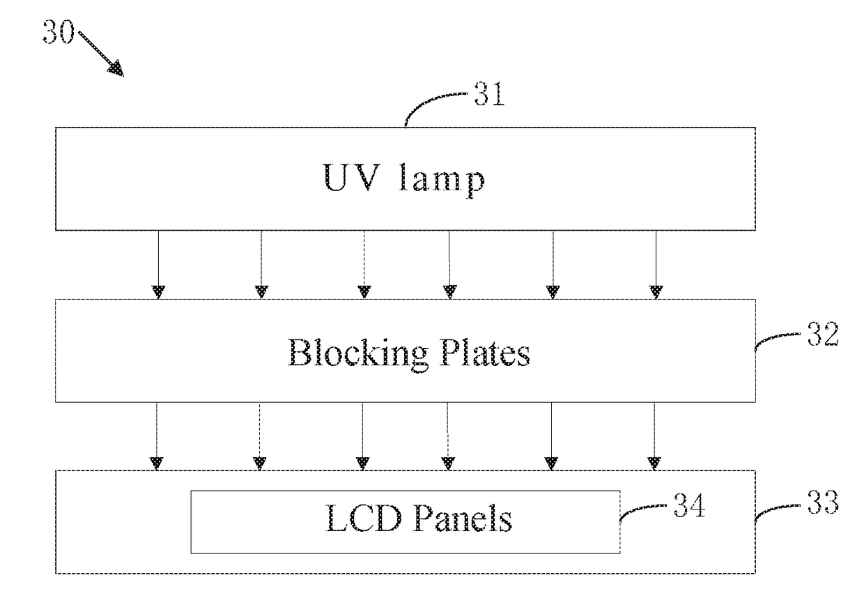
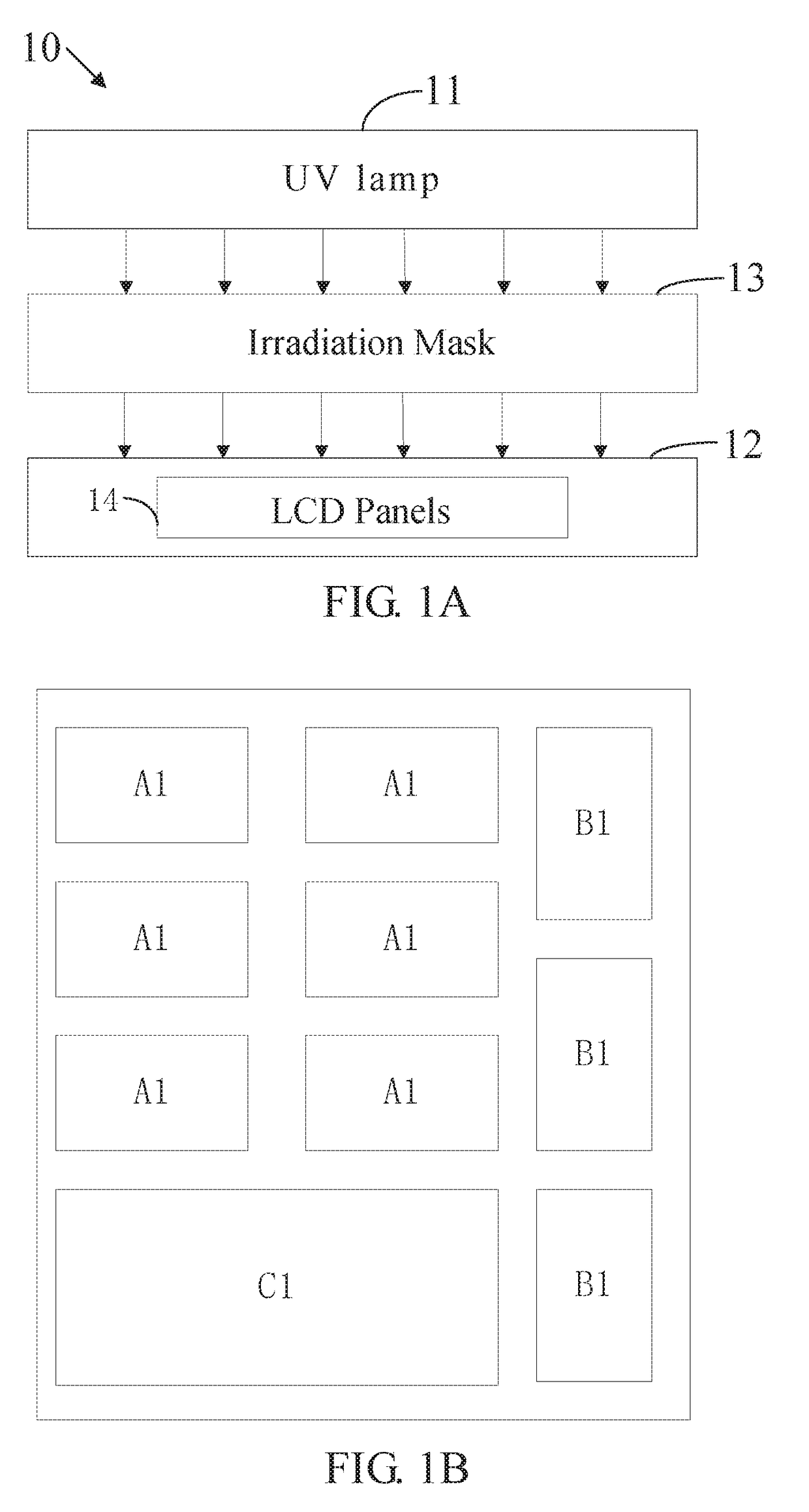
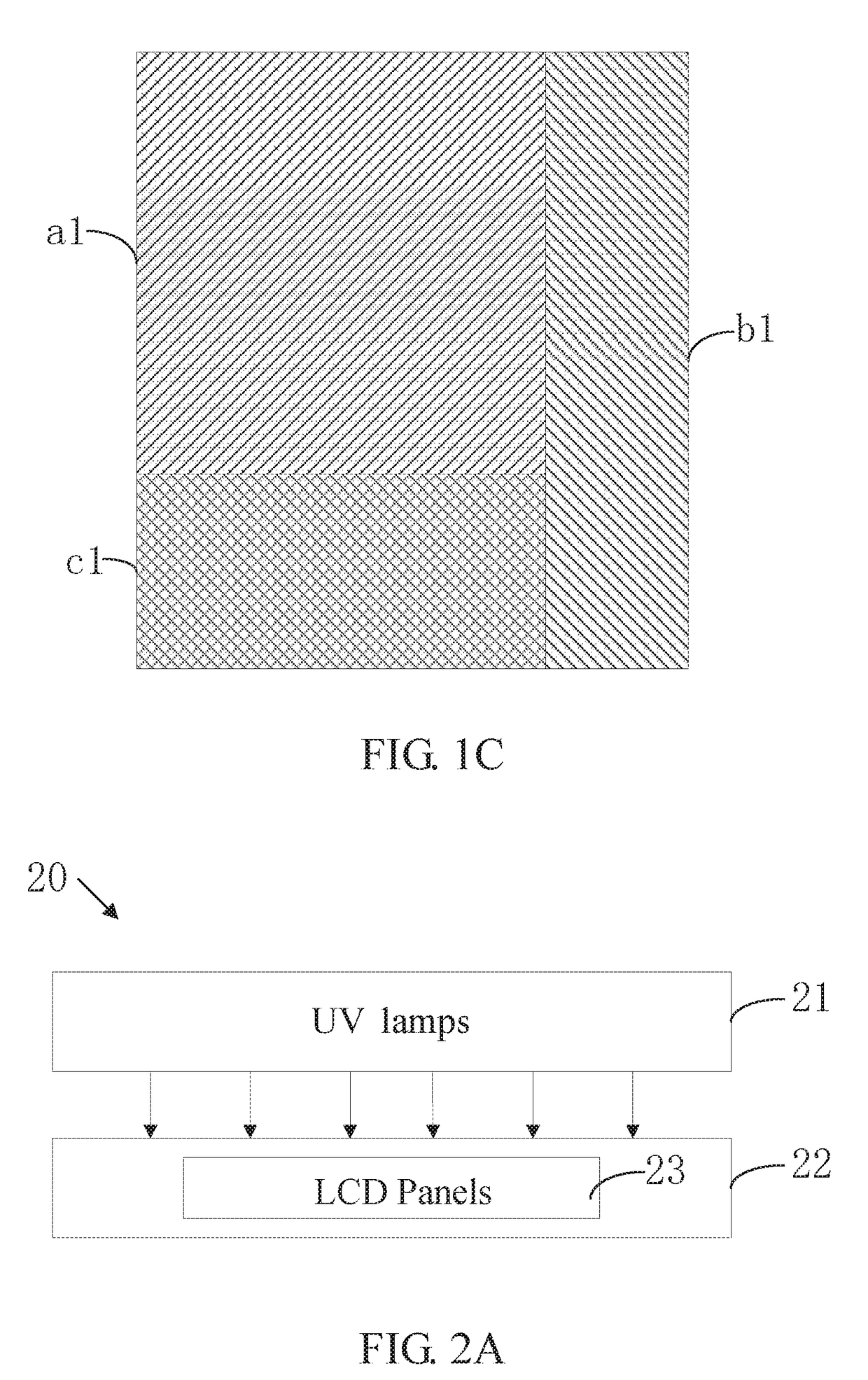
[0048]Referring to FIGS. 1A to 1C, FIG. 1A is a schematic structure of an optical alignment device for a plurality of liquid crystal display panels according to the first embodiment; FIG. 1B is a schematic arrangement of the liquid crystal panels placed on a panel carrying stage of the optical alignment device for the liquid crystal display panels according to the first embodiment; FIG. 1C is a schematic arrangement of a plurality of irradiation masks of the optical alignment device for the liquid crystal display panels according to the first embodiment of the present invention. The optical alignment device 10 of this embodiment comprises a panel carrying stage 11, a UV lamp ...


PUM

PropertyMeasurementUnit
pretilt anglesaaaaaaaaaa
transmittanceaaaaaaaaaa
sizesaaaaaaaaaa

Abstract

An optical alignment device for a plurality of liquid crystal display panels is disclosed, and has a panel carrying stage, a UV lamp, and a plurality of irradiation masks. The panel carrying stage is used for placing the liquid crystal display panels, the UV lamp is used for applying a UV irradiation to the liquid crystal display panels on the panel carrying stage so that liquid crystals in each of the liquid crystal display panels have pretilt angles, and the irradiation masks are disposed between the UV lamp and the liquid crystal display panels for changing an irradiation intensity of the UV irradiation on the crystal display panels.

Description

FIELD OF THE INVENTION[0001]The present invention relates to a liquid crystal display technology, and more particularly to an optical alignment device for a plurality of liquid crystal display panels.BACKGROUND OF THE INVENTION[0002]PSVA (polymer stabilized vertical alignment) is a technology for producing a TFT-LCD (thin film transistor-liquid crystal display). Liquid crystals in the liquid crystal display panels comprise reactive monomers which can be activated by UV irradiation, so as to form a pretilt angle of the liquid crystals. The abovementioned process is called UV optical alignment.[0003]In the UV optical alignment, the pretilt angle of the liquid crystals directly influences optical properties of the panel. When the pretilt angle is too small, the response time is too slow; when the pretilt angle is too large, the contrast of the panel is too low. The influence factors of the pretilt angle comprise UV intensity, UV irradiation time, the total amount of the UV irradiation,...

Claims


Application Information

Patent Timeline
Patent Type & Authority Applications(United States)
IPC IPC(8): G02F1/13G02F1/1337
CPCG02F1/133788G02F1/1303
Inventor ZHAO, RENTANG
Owner SHENZHEN CHINA STAR OPTOELECTRONICS TECH CO LTD
Why Eureka
Try Eureka