Mass body applicable to micro-electromechanical sensor and three-axis micro-electromechanical sensor using same

A technology of micro-electromechanical sensors and mass bodies, which is applied in the field of mass bodies and can solve the problems of sensors without capacitance changes.

Inactive Publication Date: 2011-06-22
PIXART IMAGING INC
View PDF11 Cites 4 Cited by
  • Summary
  • Abstract
  • Description
  • Claims
  • Application Information

AI Technical Summary

Problems solved by technology

But so far, there is no sensor that can simulta

Method used


Image

  • Mass body applicable to micro-electromechanical sensor and three-axis micro-electromechanical sensor using same
  • Mass body applicable to micro-electromechanical sensor and three-axis micro-electromechanical sensor using same
  • Mass body applicable to micro-electromechanical sensor and three-axis micro-electromechanical sensor using same

Examples


Embodiment Construction

[0043] The drawings in the present invention are all schematic, mainly intended to show the relative relationship between various structural parts, and the shapes, thicknesses and widths are not drawn to scale.

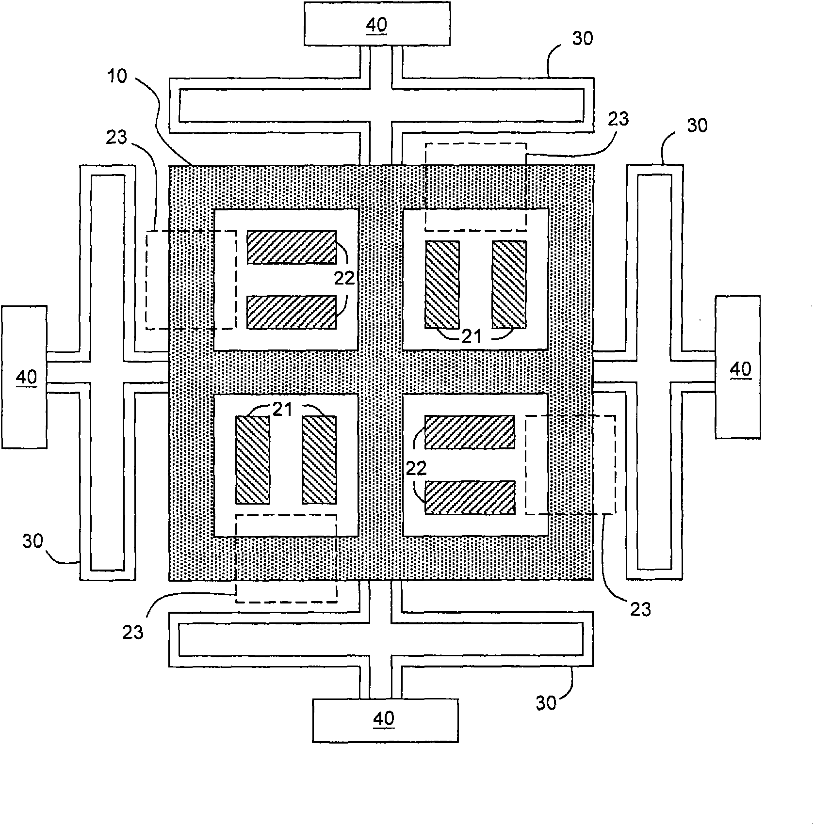
[0044] First, one of the embodiments of the present invention will be described. see Figure 1A The top view of the three-axis MEMS sensor of the present invention includes a movable electrode frame 10 , an x-axis fixed electrode 21 , a y-axis fixed electrode 22 , a z-axis fixed electrode 23 , a spring 30 , and an anchor 40 . The z-axis fixed electrode 23 and the movable electrode frame 10 are located on different horizontal planes, so they are represented by dotted lines. The fixed column 40 and the fixed electrodes 21 - 23 are fixed on the substrate (not shown), while the movable electrode frame 10 is suspended and connected to the fixed column 40 via the spring 30 .

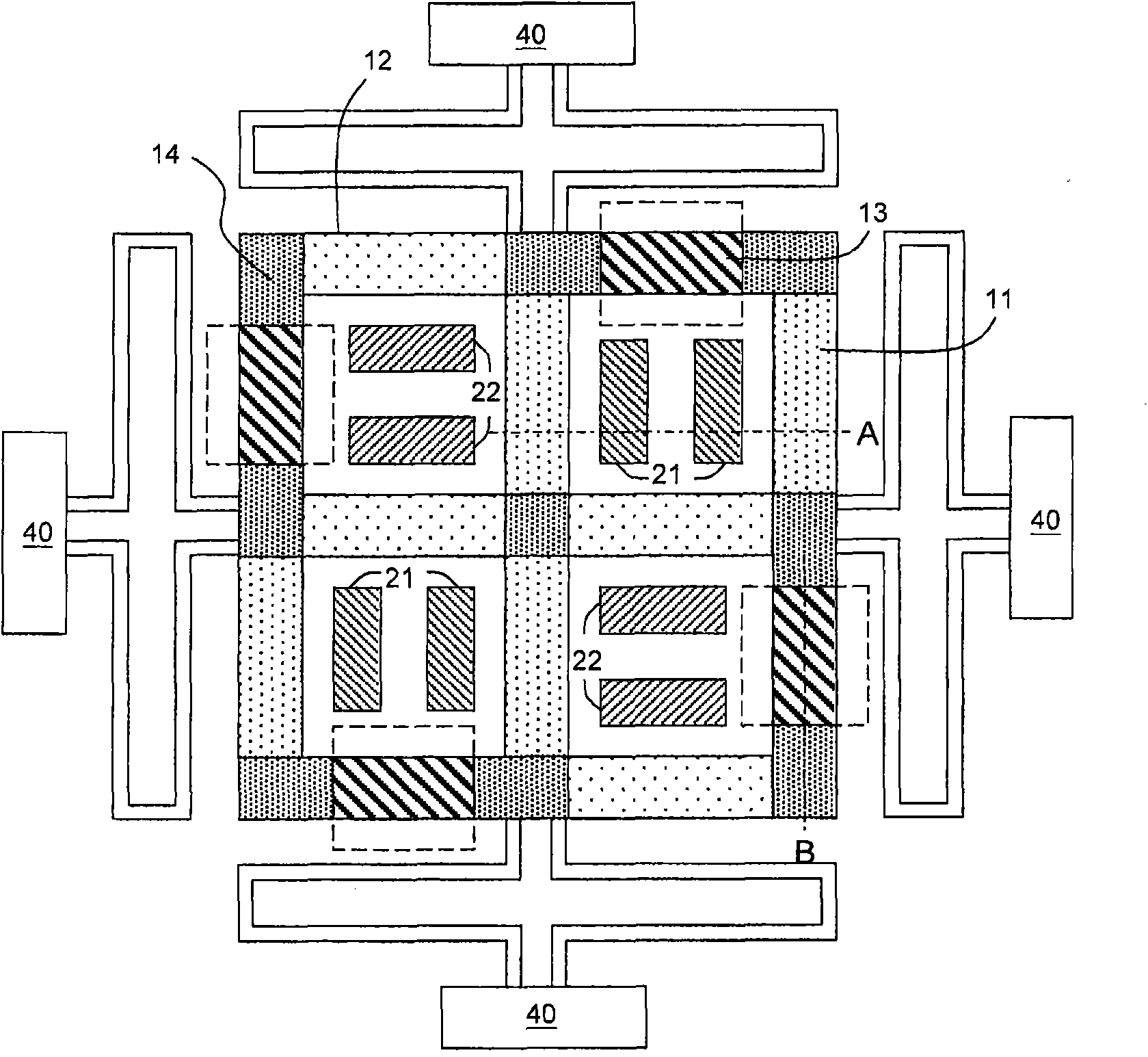
[0045] see Figure 1B , analyzing the structure of the movable electrode frame 10, it can be re...


PUM


Abstract

The invention relates to a three-axis micro-electromechanical sensor. The three-axis micro-electromechanical sensor comprises a first-axis fixed electrode, a second-axis fixed electrode, a third-axis fixed electrode, a movable electrode frame, a spring and a fixed column, wherein the movable electrode frame comprises a first-axis movable electrode, a second-axis movable electrode, a third-axis movable electrode and a connecting element for connecting the first-axis movable electrode, the second-axis movable electrode and the third-axis movable electrode together; the first-axis movable electrode and the first-axis fixed electrode form a first capacitor on a first axis; the second-axis movable electrode and the second-axis fixed electrode form a second capacitor on a second axis; the third-axis movable electrode and the third-axis fixed electrode form a third capacitor on a third axis; the connecting element comprises a central mass body which is connected with the first-axis movable electrode, the second-axis movable electrode or the third-axis movable electrode and is provided with an outer ring and a first connecting section connected with the adjacent edge of the outer ring; the spring is connected with the movable electrode frame; the fixed column is connected with the spring; and the first axis, the second axis and the third axis are not parallel to one another to define a three-dimensional coordinate system.

Description

technical field [0001] The invention relates to a mass body suitable for a microelectromechanical sensor and a three-axis microelectromechanical sensor using the mass body. Background technique [0002] MEMS components have various applications, one of which is to make capacitive sensors such as accelerometers, microphones, etc. There are two types of capacitive sensors in the prior art: in-plane sensors and out-of-plane sensors. The former senses capacitance changes in the horizontal direction (x-y plane), and the latter senses changes in the vertical direction ( The change in capacitance on the z-axis). For prior art on in-plane sensors and their manufacturing methods, for example, refer to US Patent Nos. 5,326,726, 5,847,280, 5,880,369, 6,877,374, 6,892,576, and 2007 / 0180912. Regarding the prior art of out-of-plane sensors and their manufacturing methods, for example, refer to US Patent Nos. 6,402,968, 6,792,804, 6,845,670, 7,138,694, and 7,258,011. But so far, there i...

Claims


Application Information

Patent Timeline
IPC IPC(8): B81B7/02
Inventor 王传蔚李昇达
Owner PIXART IMAGING INC
Why Eureka
Try Eureka