
Pedal electric heating fire box using heating wires

An electric heating wire and electric heating technology, applied in electric heating systems, household heating, heating methods, etc., can solve the problems of large thermal stress deformation, high manufacturing cost, reduced insulation performance, etc., achieve uniform thermal stress deformation, and eliminate temperature unevenness. , The effect of small thermal stress deformation

Inactive Publication Date: 2011-06-22
袁亮
View PDF0 Cites 1 Cited by
  • Summary
  • Abstract
  • Description
  • Claims
  • Application Information

AI Technical Summary

Problems solved by technology

But it has following deficiencies: the one, complex structure
Existing electric heating pedal heating firebox, its electric heating device is generally a quartz tube electric heating device, the structure is more complicated, and the manufacturing cost is relatively high; the second is not safe enough
On the one hand, the quartz tube in the electric heating device is easily broken, which may cause unsafety; The electric heating device is generally installed in the middle of the bottom plate of the box body. The temperature above the electric heating device is relatively high, and the temperature of the footboard above the corresponding electric heating device is also relatively high. The temperature of other parts in the box body is relatively low. It is impossible to install the thermostat and fuse on the lower surface of the footboard above the electric heating device. Therefore, when the temperature detected by the thermostat and the fuse reaches its nominal temperature, the local temperature of the footboard above the electric heating device It may have greatly exceeded the nominal temperature of the thermostat and fuse. In special cases covered by quilts, the quilts and other clothes may be damaged or even cause a fire.
[0003] Existing electric heating fireboxes that utilize electric heating wires as heating elements are generally installed on the lower surface of the footboard made of good thermal conductors, but they also have deficiencies: 1. There is a safety Hidden dangers; one is that the insulation between the heating wire and the footboard is only one layer of silicone rubber made of insulating cladding, especially after a period of use, after the silicone rubber ages, its insulation performance is greatly reduced, which may cause electric leakage on the footboard , making it unsafe for the human body to step on the pedals for heating; the second is that the heating element of the electric heating wire is closely installed on the lower surface of the footboard, and the local temperature at the place where the heating wire heating element is installed is relatively high, and most of the other parts of the footboard The temperature is relatively low, and in order to ensure the heating effect of the entire firebox, the local temperature where the heating element is installed may be higher than the suitable heating temperature for the human body, especially when the weather is cold and a higher temperature is required for heating. The local temperature of the heating element with the electric heating wire will be higher. In this way, stepping directly on it may feel hot, and may even burn the delicate skin of the child.
2. The local thermal stress and deformation of the footboard are relatively large during use
Because the electric heating wire heating element is installed closely on the lower surface of the footboard, the local temperature at the place where the electric heating wire heating element is installed is relatively high, and the temperature of most other parts of the footboard is relatively low. During use, the temperature of the entire footboard The thermal stress deformation is different, and the local thermal stress deformation is large at the place where the electric heating wire heating element is installed, so that the footboard will protrude locally, which will affect the comfort and use

Method used


Image

  • Pedal electric heating fire box using heating wires
  • Pedal electric heating fire box using heating wires

Examples


Embodiment Construction

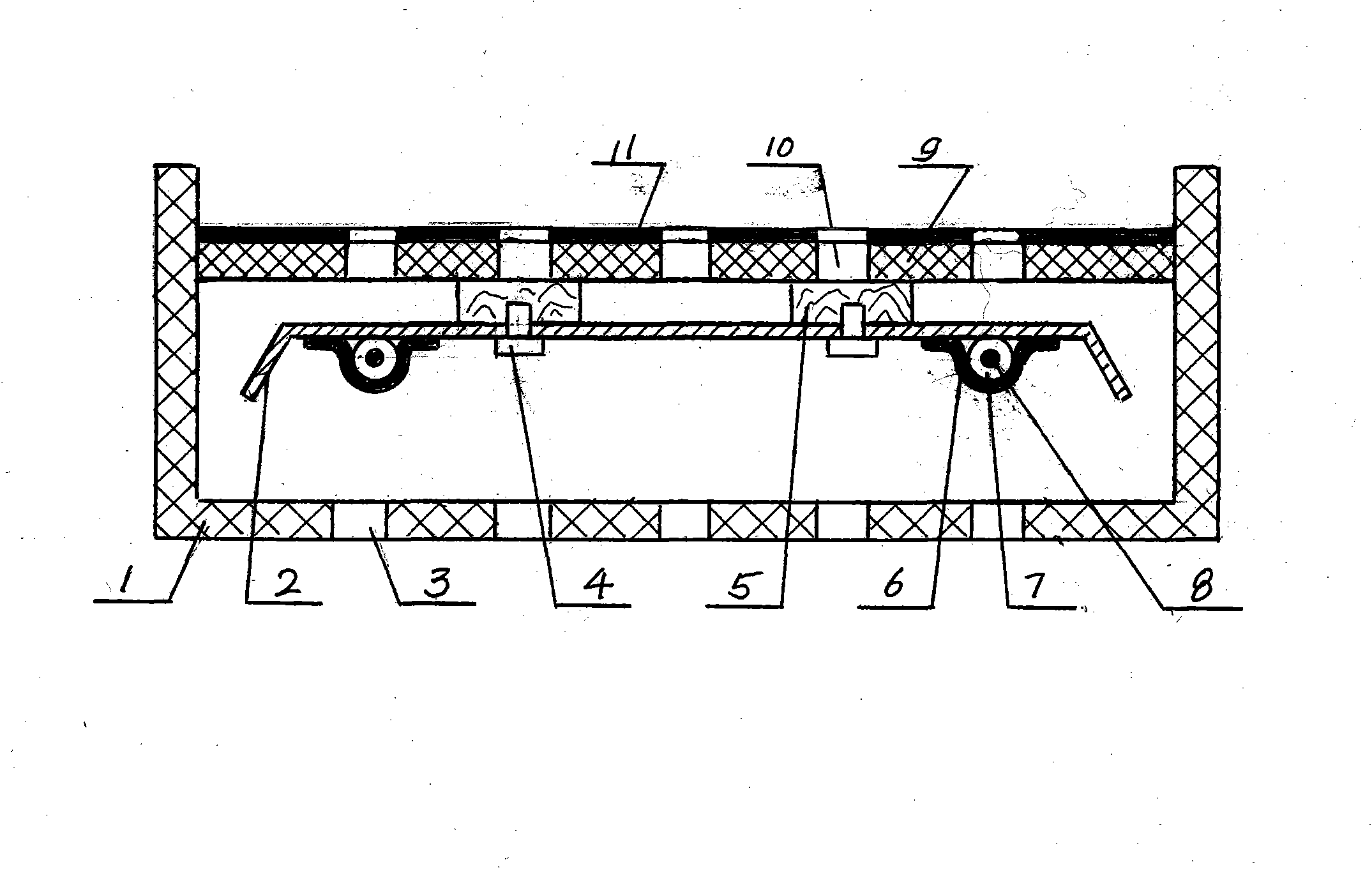
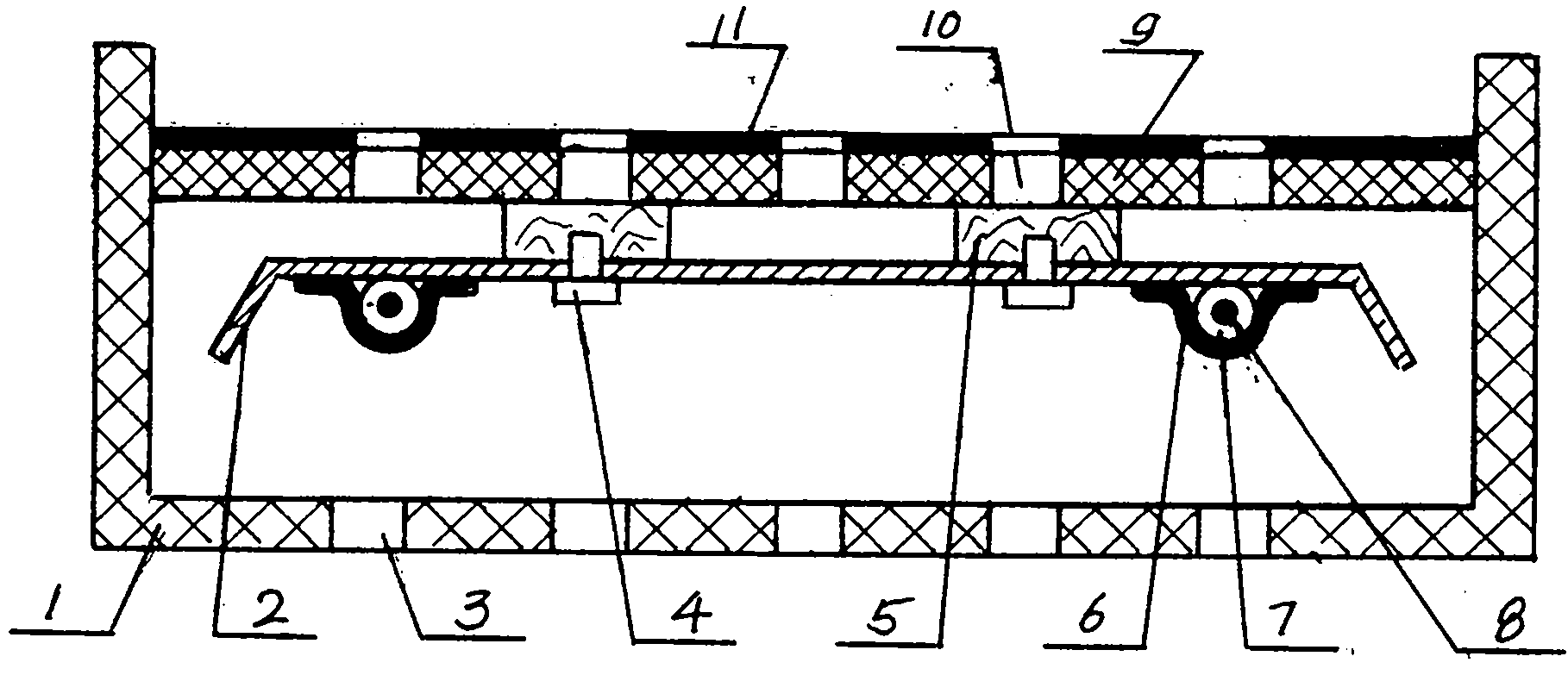
[0019] As shown in the figure, the box body 1 includes a closed peripheral wall and a bottom plate installed at its lower end, on the bottom plate is provided with bottom plate ventilation holes 3, on the box body 1, a support rod 5 is installed, and the support rod 5 is made of insulating material , a tread plate 9 made of a good conductor of heat is provided on the support rod 5, a tread plate ventilation hole 10 is provided on the tread plate 9, an electrostatic flocking cushion layer 11 is provided on the tread plate 9, and an electrostatic flocking cushion layer 11 is provided on the tread plate 9. 5. The heat conduction plate 2 is installed on the bottom through the fastening screw 4. The distance between the lower surface of the support rod 5 and the upper surface of the heat conduction plate 2 is designed to be 20MM. The heat conduction plate 2 is made of a good conductor of heat. On the surface, there is an electric heating device installed in close contact with sticke...


PUM


Abstract

The invention discloses a pedal electric heating fire box using heating wires, comprising a box body (1), wherein the peripheral wall of the box body (1) is closed, the lower end of the box body (1) is provided with a bottom plate, the upper end of the box body (1) is open, the bottom plate is provided with bottom plate air vents (3), the box body (1) is internally provided with a foot pedal (9) made of a good heat conductor, the foot pedal (9) is provided with foot pedal air vents (10), a heat conducting plate (2) is installed below the foot pedal (9), the heat conducting plate (2) and the foot pedal (9) are in a mutual insulating structure form, heating elements are installed on a lower side surface of the heat conducting plate (2) in an appressed way and respectively comprise the heating wire (8) and an insulating layer (7) coated at the outer layer of the heating wire (8), the maximum electric power of the heating element per 100 millimeters is 15W under the conditions of rated voltage and rated current, a temperature controller and a fuse protector are installed on the heat conducting plate (2), and a temperature controller is installed on the foot pedal (9). The pedal electric heating fire box using the heating wires has the advantages of safety in use, comfortableness, low manufacturing cost and energy saving.

Description

technical field [0001] The invention relates to an electric heating wire electric heating pedal heating firebox. Background technique [0002] Existing electric heating foot heating fire box includes a box body with closed surrounding walls and bottom and an open upper end. A footboard made of thermal non-good conductors such as wood is installed in the box body. Electric heating device, when heating, the open end cover quilt of the box body, the electric heating device generates heat, and the human body is heated on the top of the footboard and under the quilt, thus forming a relatively closed space between the quilt and the box body. Reduce heat dissipation and save energy. But it has following deficiencies: the one, complex structure. Existing electric heating foot heating fire box, its electric heating device is generally a quartz tube electric heating device, the structure is more complicated, and the manufacturing cost is relatively high; the other is not safe enough...

Claims


Application Information

Patent Timeline
Patent Type & Authority Applications(China)
IPC IPC(8): F24D13/02F24D19/08F24D19/10
Inventor 袁亮
Owner 袁亮
Learn More