Method and device for timing shift estimation

A technology of timing offset estimation and timing offset, which is applied in the field of communication, can solve the problems of large number of IDFT points and high computational complexity, and achieve the effect of reducing complexity and avoiding a large number of zero padding

Active Publication Date: 2011-06-22
ZTE CORP
View PDF3 Cites 12 Cited by
  • Summary
  • Abstract
  • Description
  • Claims
  • Application Information

AI Technical Summary

Problems solved by technology

[0006] The purpose of the present invention is to provide a timing offset estimation method and device to solve the problem in the related art that when estimating the timing offset, in order to improve the time domain resolution or timing accuracy, the number of IDFT points used is large and the calculation complexity is high.

Method used


Image

  • Method and device for timing shift estimation
  • Method and device for timing shift estimation
  • Method and device for timing shift estimation

Examples


example 1

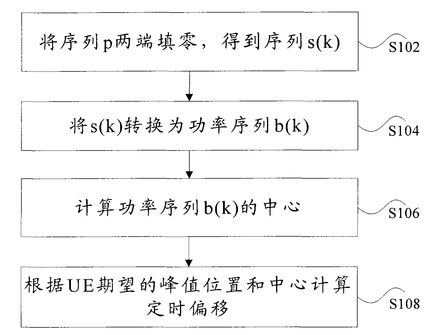
[0038] In the following, the predetermined channel is PRACH as an example, and the above timing offset estimation method is described in detail through specific examples.

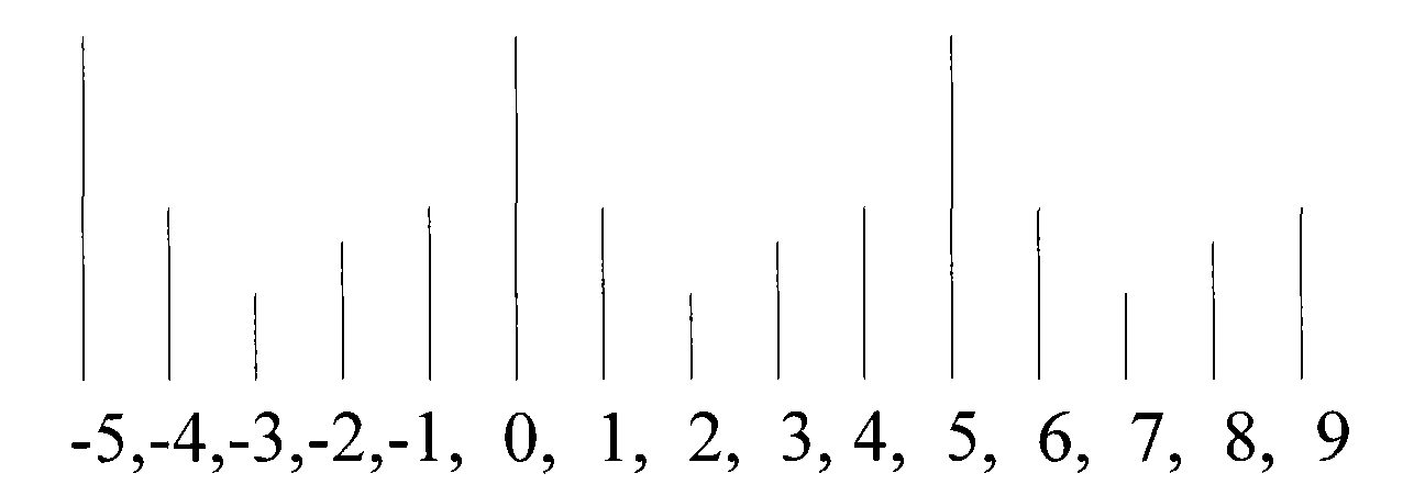
[0039] Perform zero-fill operation on the sequence p with a length of 839 to obtain a sequence s(k) with a length of 864. After performing IDFT transformation on the sequence s(k) with 864 points, the obtained time domain signal is g(k). Calculate Its power value is 5, 22, 50, 30, 15, 0, 0, ... in turn.

[0040] Comparing the various power values, the position where the maximum value appears is w=2.

[0041] The window length is taken as K=2, then the position of the center of gravity is (5*0+22*1+50*2+30*3+15*4) / (5+22+50+30+15)=2.2295.

[0042] The expected peak position of the UE is 0, then the timing offset is TA=(0-2.2295)*24576 / 864=-63.4Ts, and TA=-63 through rounding. If it is considered that the actual TA control command accuracy is a resolution of 16Ts, it can be further processed.

example 2

[0044] This example describes that the coordinates of the left and right windows exceed the range [0, M-1] (ie, w-iM-1) and (d 0 -d w ) is a detailed processing procedure when it exceeds the interval [-M / 2, M / 2].

[0045] For example, the signal power values ​​of 864 points in the time domain are 30, 15, 0, 0, ..., 0, 0, 5, 22, 50 in sequence. Comparing the various power values, the position where the maximum value appears is w=863. If the window length is K=2, then the coordinates of the two points in the right window become 864 and 865. The position of the center of gravity is (5*861+22*862+50*863+30*864+15*865) / (5+22+50+30+15)=863.2295. The expected peak position of the UE is 0, and the offset is 0-863.2295=-863.2295.

[0046] This value is out of the range [-432, 432]. After adjustment, the adjusted offset is -863.2295+864=0.7705, and the timing offset is TA=0.7705*24576 / 864=21.9164Ts. After rounding, we finally get TA=22.

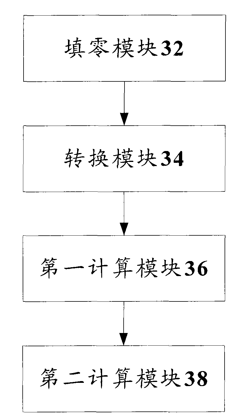
[0047] The timing offset estimation method...


PUM


Abstract

The invention discloses a method and device for timing shift estimation. The method comprises a step of filling zero at two ends of a sequence p, so as to acquire a sequence s(k), wherein the sequence p is a result of conjugate multiplication between a frequency domain mark received on a preset channel by user equipment (UE) and a Zadoff-Chu sequence; k is equal to 0,...,M-1; M is the number of sub-carriers occupied by signals in the preset channel; and the preset channel comprises a PRACH (physical random access channel) or a PUSCH (physical uplink shared channel). The method further comprises the following steps: converting s(k) into a power sequence b(k); calculating the center of the power sequence b(k); and calculating the timing shift according to the expected peak position of UE and the center. By using the method and device provided by the invention, the complex rate of calculation is reduced.

Description

technical field [0001] The present invention relates to the communication field, in particular to a timing offset estimation method and device. Background technique [0002] In a Long Term Evolution (referred to as LTE) system, in order to achieve uplink synchronization, a base station (evolved NodeB, referred to as eNB or eNodeB) needs to send an uplink signal from each user equipment (User Equipment, referred to as UE). Synchronization is reached at the base station, so each UE's timing offset must be estimated and the UEs then ordered to adjust their transmit times. [0003] In the related art, there are several methods for obtaining the timing offset, and different methods have different implementation complexity and estimation accuracy. For example, the Physical Random Access Channel (PRACH) channel in LTE is used for uplink random access, the base station detects the PRACH signal sent by the UE, and the initial timing offset can be estimated through the PRACH; or, Th...

Claims


Application Information

Patent Timeline
Patent Type & Authority Applications(China)
IPC IPC(8): H04W56/00H04B7/26
Inventor 李杰殷玮玮
Owner ZTE CORP
Why Eureka
Try Eureka