Turbomachine fan rotor

A fan rotor, turbine technology, applied in the direction of mechanical equipment, engine components, machines/engines, etc., can solve unsatisfactory, wear and other problems

Active Publication Date: 2011-06-22
SN DETUDE & DE CONSTR DE MOTEURS DAVIATION S N E C M A
View PDF7 Cites 7 Cited by
  • Summary
  • Abstract
  • Description
  • Claims
  • Application Information

AI Technical Summary

Problems solved by technology

However, this solution is not satisfactory, since the blade root thus has an axial dimension shorter than that of the slot in the disc, which may lead to its advance when high contact forces are applied to the side walls of the slot risk of wear and tear

Method used


Image

  • Turbomachine fan rotor
  • Turbomachine fan rotor
  • Turbomachine fan rotor

Examples


Embodiment Construction

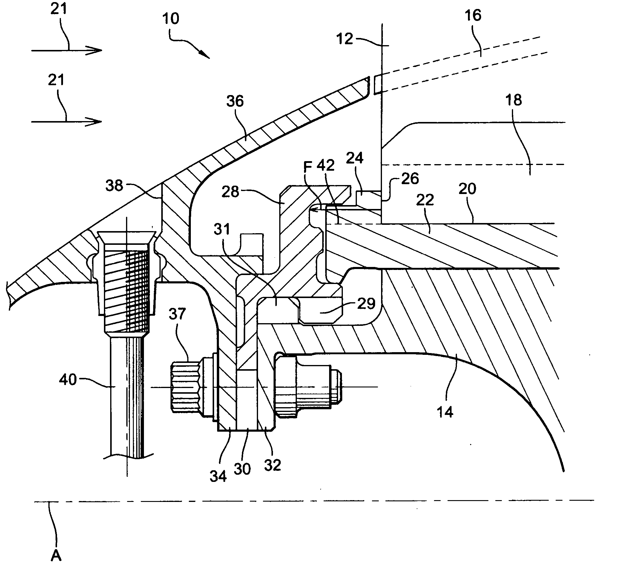
[0024] see first figure 1 , which shows a prior art turbomachine fan rotor 10 prior to the present invention.

[0025] The fan rotor 10 comprises blades 12 carried by a disc 14 secured to the upstream end of a shaft (not shown) of the turbine, with an interblade platform 16 interposed between the blades.

[0026] Each fan blade 12 comprises an airfoil connected at its radially inner end to a root 18 which engages in a complementary shaped generally axial slot 20 in the disk 14 for retaining the blade radially on the disk. superior.

[0027] The inter-blade platforms 16 form walls defining the inside of the air flow 21 entering the turbine, and they include means between the slots 20 cooperating with corresponding means provided on the disc 14 for fastening the platforms to the disc.

[0028] A spacer 22 is interposed between the root 18 of each blade and the bottom of a corresponding slot 20 in the disk to prevent radial movement of the blade in the slot. Each spacer 22 is ...


PUM


Abstract

The invention relates to a turbomachine fan rotor (10) including a disc (14) bearing blades (12') having roots (18') fitted into axial slots (20) in the disc and a wedge (22') which is inserted between the base of each slot and the corresponding blade root and which is provided with a blade root retaining spoiler (24') at the upstream end thereof, said spoiler including a downstream abutment face against which the upstream end of the blade root presses in the event of a violent force and which is oblique with respect to the axis (A) of rotation of the rotor.

Description

technical field [0001] The present application relates to fan rotors for use in turbomachines, such as aircraft turboprops or turbojets. Background technique [0002] A turbomachine fan includes a disk carrying blades at an outer periphery, the blades having roots that engage in generally axial grooves in the outer periphery of the disk. The blades are held radially on the disk by the fit between the shape of their roots, for example dovetail-shaped, and the shape of the grooves in the disk. [0003] A spacer is interposed between the root of each blade and the bottom of the corresponding slot in the disk to prevent the blades from moving radially in the disk, the spacer having a prong at its upstream end extending radially outward , and has a downstream radial face forming an axial bearing surface against the upstream radial face of the blade root to axially retain the blade in the upstream direction. The spacers ensure that the blades on the disc all have the same axial ...

Claims


Application Information

Patent Timeline
Patent Type & Authority Applications(China)
IPC IPC(8): F01D5/30
CPCY02T50/671F01D5/323Y02T50/60
Inventor 泽维尔·路易斯·巴赛莱梅·米利尔里吉斯·尤金·亨利·赛文特飞利浦·威塞克斯
Owner SN DETUDE & DE CONSTR DE MOTEURS DAVIATION S N E C M A
Why Eureka
Try Eureka