Part-load control in a split-cycle engine

一种发动机、动力的技术,应用在燃烧发动机、机器/发动机、机械设备等方向

Inactive Publication Date: 2011-06-22
SKADERI GRUP LLC
View PDF7 Cites 1 Cited by
  • Summary
  • Abstract
  • Description
  • Claims
  • Application Information

AI Technical Summary

Problems solved by technology

However, controlling the load in this way may have the adverse effect of

Method used


Image

  • Part-load control in a split-cycle engine
  • Part-load control in a split-cycle engine
  • Part-load control in a split-cycle engine

Examples


Embodiment Construction

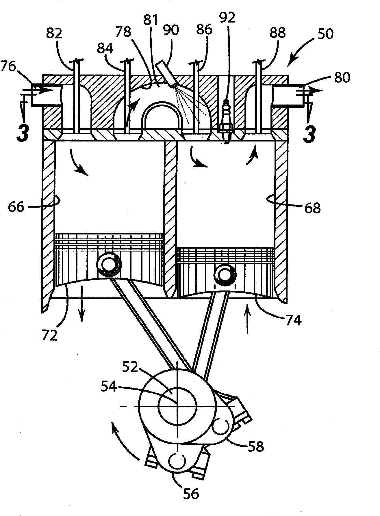
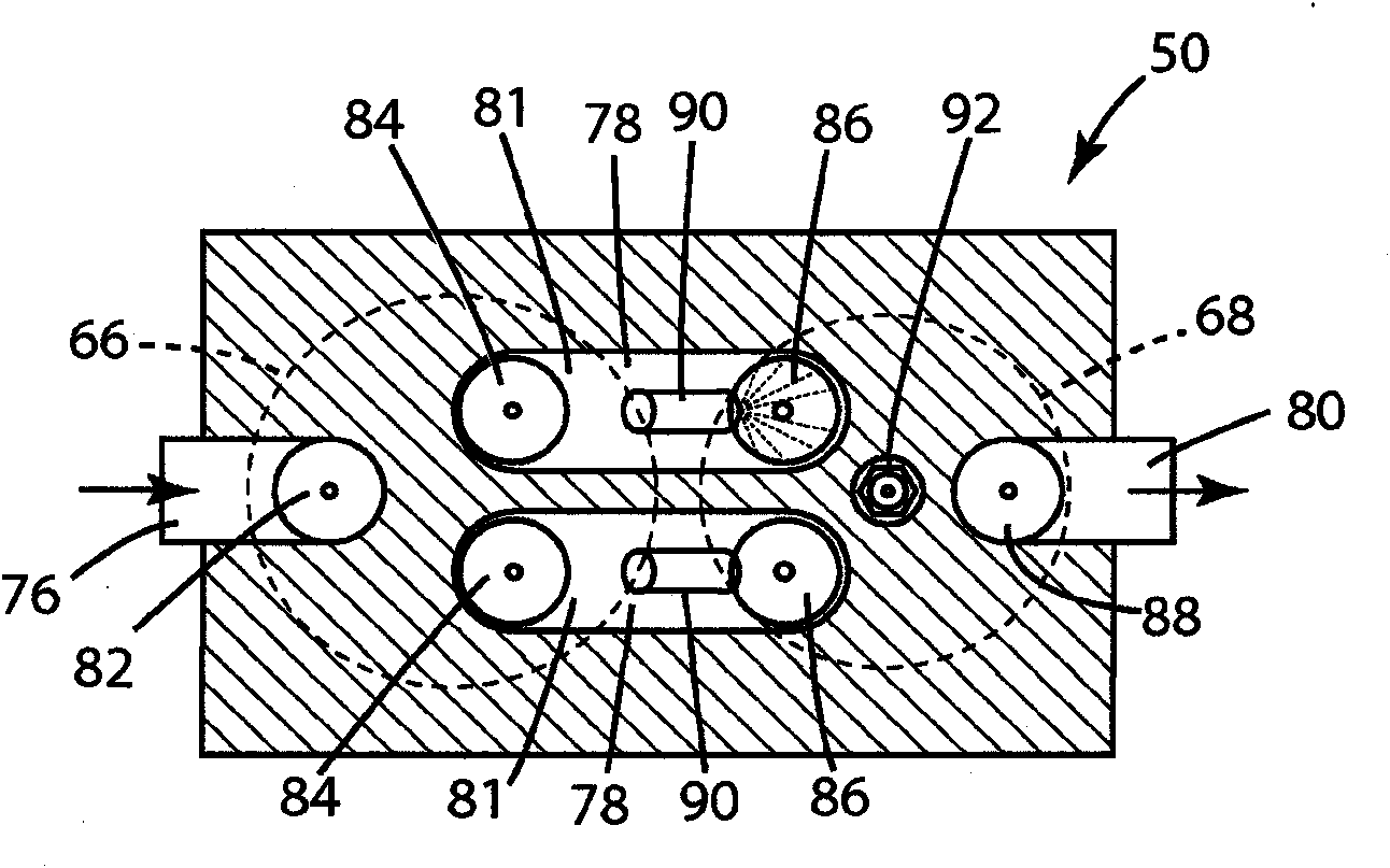
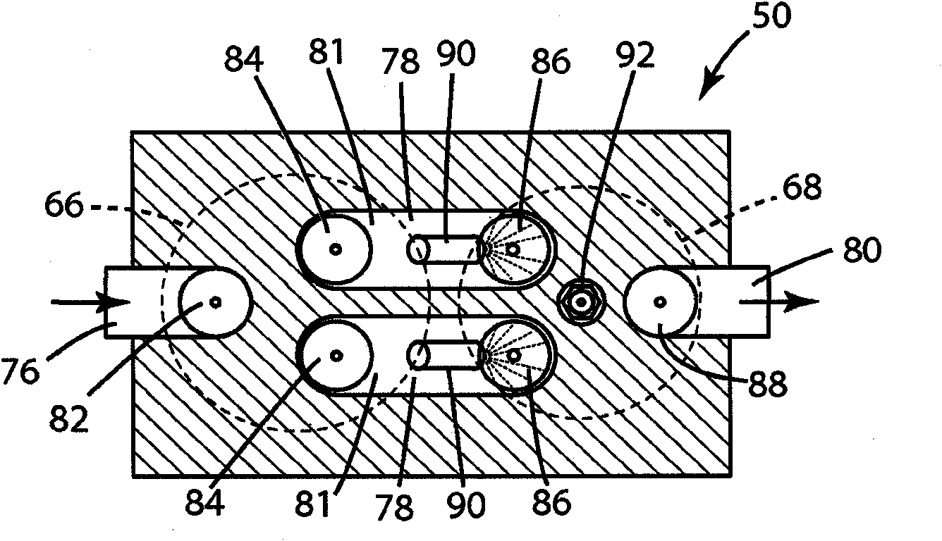
[0031] refer to figure 1 , numeral 50 generally denotes a split-cycle engine according to the invention. Split-cycle engine 50 includes a crankshaft 52 rotatable about a crankshaft axis 54 . Compression piston 72 is slidably received within compression cylinder 66 and is operatively connected to crankshaft 52 such that compression piston reciprocates through an intake stroke and a compression stroke during a single revolution of the crankshaft. Expansion (power) piston 74 is slidably received within expansion cylinder 68 and is operatively connected to crankshaft 52 such that the expansion piston reciprocates through the expansion stroke and the exhaust stroke during a single revolution of the crankshaft. At least two bridging passages 78 interconnect the expansion cylinder 66 and the compression cylinder 68 . Each crossover passage includes a crossover compression (XovrE) valve 84 and a crossover expansion (XovrE) valve 86 operable to define a pressure chamber 81 therebetwe...


PUM


Abstract

An engine includes a crankshaft rotatable about a crankshaft axis. A compression piston is slidably received within a compression cylinder and operatively connected to the crankshaft such that the compression piston is operable to reciprocate through an intake stroke and a compression stroke during a single rotation of the crankshaft. An expansion (power) piston is slidably received within an expansion cylinder and operatively connected to the crankshaft such that the expansion piston is operable to reciprocate through an expansion stroke and an exhaust stroke during a single rotation of the crankshaft. At least two crossover passages interconnect the compression and expansion cylinders. Each of the at least two crossover passages includes a crossover compression (XovrC) valve and a crossover expansion (XovrE) valve operable to define a pressure chamber therebetween. The engine controls and maximizes engine efficiency at part-load by utilizing only selected crossover passages.

Description

technical field [0001] The present invention generally relates to controlling and maximizing the efficiency of split cycle engines operating under part load conditions. Background technique [0002] For clarity, the term "conventional engine" is used in this application to denote all four strokes (i.e., intake stroke, compression stroke, expansion stroke) of the Otto or Diesel cycle in which it is known. and exhaust stroke) are included in each piston / cylinder combination of the engine in an internal combustion engine. Each stroke requires half a crankshaft rotation (180 degrees crank angle (CA)) and two full crankshaft revolutions (720 degrees CA) to complete a complete Otto or Diesel cycle in each cylinder of a conventional engine . [0003] In addition, for the sake of clarity, the term "split-cycle engine" applied to engines disclosed in the prior art and referred to in this application is defined as follows. [0004] Split-cycle engines mainly include: [0005] a cr...

Claims


Application Information

Patent Timeline
Patent Type & Authority Applications(China)
IPC IPC(8): F02B33/30
CPCF02B2075/025F02B33/22F02B3/02F02B33/44F02B75/02F02B75/18F02B75/32
Inventor 斯蒂芬·史古德利
Owner SKADERI GRUP LLC
Why Eureka
Try Eureka