Constant temperature internal combustion engine and method

a constant temperature, internal combustion engine technology, applied in the direction of combustion engines, positive displacement engines, hot gas positive displacement engine plants, etc., can solve the problems of high fuel cost, pollution, and many concerns, so as to reduce the production of co, and reduce the production of long burn time

Inactive Publication Date: 2007-12-20
ZAJAC OPTIMUM OUTPUT MOTORS
View PDF72 Cites 26 Cited by
  • Summary
  • Abstract
  • Description
  • Claims
  • Application Information

AI Technical Summary

Benefits of technology

[0008] Another object of the invention is to provide an internal combustion engine and method of the above character which operate efficiently over a wide range of operating and load conditions.
[0018] The amount of air and fuel provided to the combustion chamber can be adjusted for different load conditions. The timing for the intake valve controls the amount of air taken into the engine, and the timing of the outlet valve assures that the compressed air is at the correct pressure when the air is pushed into the combustion chamber. The timing for the inlet valve and the exhaust valve can also be adjusted according to the load. In some embodiments, the same amount of air is pumped into the compression chamber at different loads, but the amount of fuel injected and the amount of gas admitted to the expansion chamber are reduced at lower loads. The inlet valve to the expansion chamber is allowed to remain open for a shorter period of time at lower loads, with the pressure in the expansion chamber reaching atmospheric pressure before the piston reaches bottom dead center. This results in below atmospheric pressure as the piston continues its downward cycle, but the opening of the exhaust valve is delayed past bottom dead center to allow this negative work to be recovered during the upward cycle of the piston. In this way, efficiency is maintained across a wide range of load conditions.
[0019] In some embodiments, compression release braking is provided using either or both the compression cylinder and expansion cylinder. In one embodiment, compressed air is allowed to escape from the compression cylinder into the intake manifold to provide compression release braking without requiring an external muffler. In another embodiment, compression release braking is provided using both the compression cylinder and expansion cylinder in a manner that allows air to be compressed in at least one cylinder on every revolution of the crankshaft.
[0020] In some embodiments, the combustion chamber allows fuel to be ignited and then diluted with additional air to produce a leaner fuel mixture and reduce the production of CO. The combustion chamber also provides a relatively long burn time to reduce the production of CO. In some embodiments, the temperature of the combustion chamber is between about 1400 and 1800° K, which is hot enough to ensure that all of the burn products are oxidized and cool enough to prevent the formation of NOX. Consequently, the exhaust from the engine is essentially free of CO and NOX. The long burn time is beneficial in preventing unburned hydrocarbons and soot from being discharged in the exhaust.

Problems solved by technology

Attempts to set the valving, stroke, and fuel delivery at targets that provide both power and efficiency are, by design, compromises of both.
When different load conditions are factored in, the compromises may become even greater.
With today's engines, there is much concern about pollution and the high cost of fuel.

Method used


Image

  • Constant temperature internal combustion engine and method
  • Constant temperature internal combustion engine and method
  • Constant temperature internal combustion engine and method

Examples


Embodiment Construction

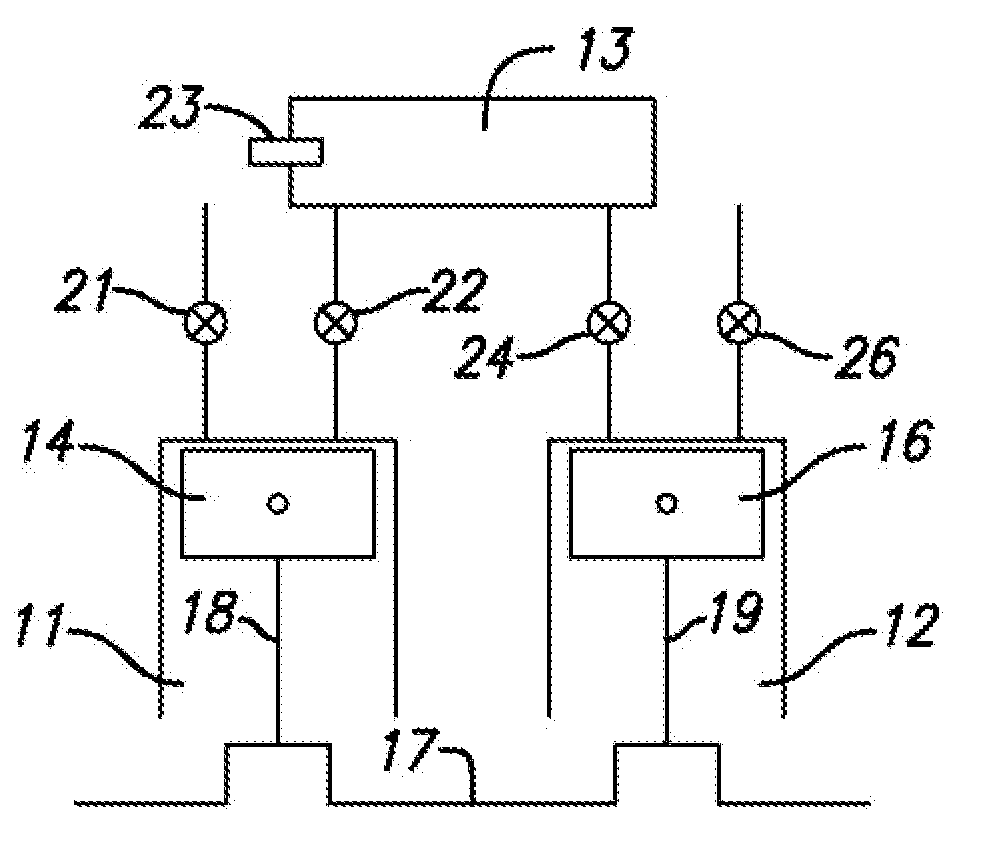
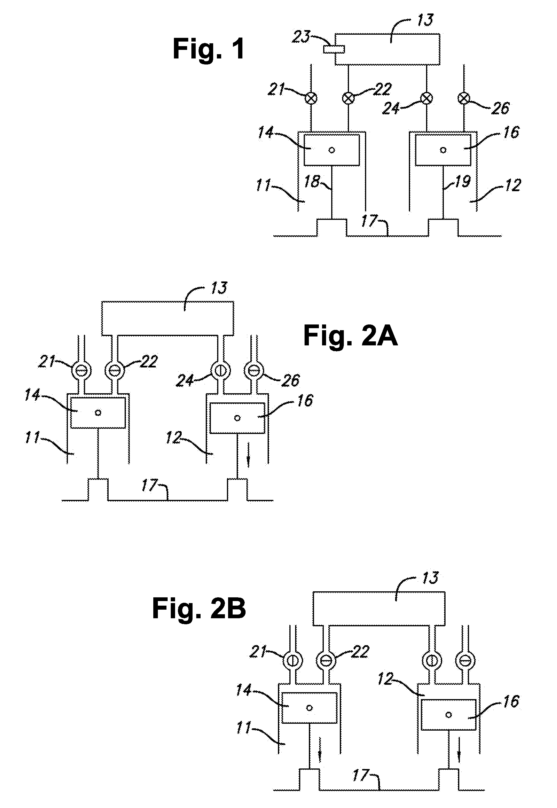
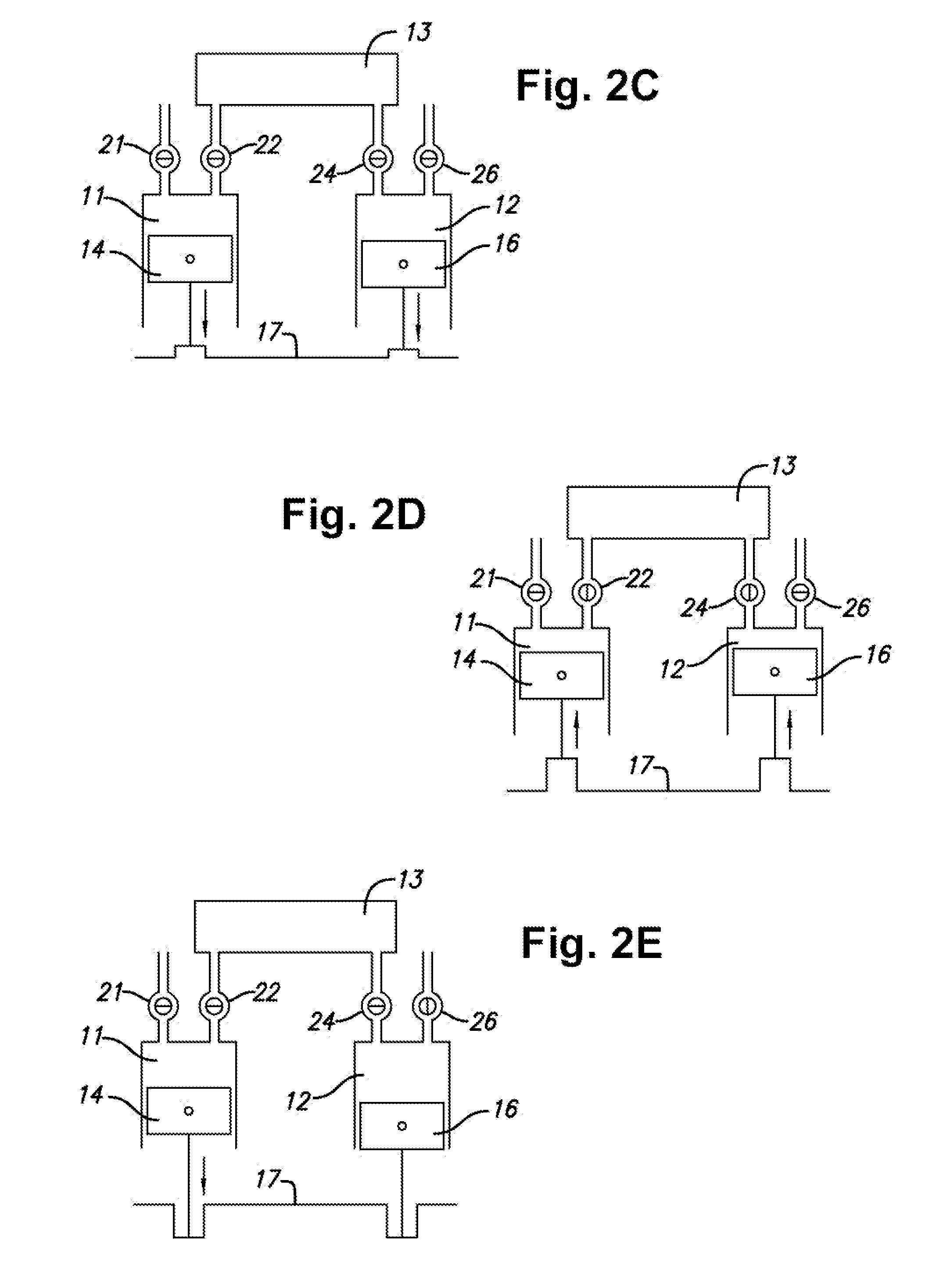
[0032] In the embodiment illustrated in FIG. 1, the engine has a compression cylinder 11 and an expansion cylinder 12 which communicate with opposite ends of a combustion chamber 13, with reciprocating pistons 14, 16 in the two cylinders forming chambers of variable volume. The pistons are connected to a crankshaft 17 by connecting rods 18, 19 for movement in concert between top dead center (TDC) and bottom dead center (BDC) positions in the cylinders, with each of the pistons making one upstroke and one downstroke during each revolution of the crankshaft. The terms upstroke and downstroke, as used herein, refer to the direction of piston movement toward the positions of minimum and maximum cylinder volume, not the physical directions in which the pistons travel.

[0033] Compression cylinder 11 receives fresh air through an intake valve 21 and communicates with the inlet end of combustion chamber 13 through an outlet valve 22. Fuel is injected into the combustion chamber through a fu...


PUM


Abstract

Internal combustion engine and method with compression and expansion chambers of variable volume, a combustion chamber, a variable intake valve for controlling air intake to the compression chamber, a variable outlet valve for controlling communication between the compression chamber and the combustion chamber, means for introducing fuel into the combustion chamber to form a mixture of fuel and air which burns and expands in the combustion chamber, a variable inlet valve for controlling communication between the combustion chamber and the expansion chamber, a variable exhaust valve for controlling exhaust flow from the expansion chamber, means for monitoring temperature and pressure conditions, and a computer responsive to the temperature and pressure conditions for controlling opening and closing of the valves and introduction of fuel into to the combustion chamber to optimize engine efficiency over a wide range of engine load conditions. In some disclosed embodiments, the relative volumes of the compression and expansion chambers and the timing of the valves are such that the pressure in the combustion chamber remains substantially constant throughout the operating cycle of the engine, and exhaust pressures are very close to atmospheric pressure regardless of the load on the engine. In others, the temperature within the combustion chamber is maintained at a substantially constant level throughout the operating range of the engine, and the power produced by the engine is determined by the amount of air passing through the engine. The engine runs so quietly and burns so cleanly that in some applications it may not require a muffler and / or a catalytic converter.

Description

RELATED APPLICATIONS [0001] Continuation-in-part of Ser. No. 11 / 372,751, Filed Mar. 9, 2006; Provisional Application No. 60 / 806,204, filed Jun. 30, 2006, the priority of which is claimed.BACKGROUND OF THE INVENTION [0002] 1. Field of Invention [0003] This invention pertains generally to internal combustion engines and, more particularly, to an internal combustion engine and method capable of operating with high efficiency over a wide range of engine speeds and load conditions. [0004] 2. Related Art [0005] Heretofore, engines have been designed for specific uses. Gasoline engines may, for example, be designed to maximize power or efficiency. Attempts to set the valving, stroke, and fuel delivery at targets that provide both power and efficiency are, by design, compromises of both. When different load conditions are factored in, the compromises may become even greater. [0006] With today's engines, there is much concern about pollution and the high cost of fuel. To find a solution to t...

Claims


Application Information

Patent Timeline
Patent Type & Authority Applications(United States)
IPC IPC(8): F02B75/16
CPCF02B41/02Y02T10/42F02B41/06Y02T10/40
Inventor ZAJAC, JOHNCHAND, JAMES PETER
Owner ZAJAC OPTIMUM OUTPUT MOTORS
Why Eureka
Try Eureka