Sludge scraper for clarifier

A mud scraper and clarifier technology, applied in chemical instruments and methods, settling tanks, feeding/discharging devices of settling tanks, etc., can solve the problems of large-scale clarifiers, low efficiency, and long time

Inactive Publication Date: 2011-06-29
丁海荣 +1
View PDF4 Cites 4 Cited by
  • Summary
  • Abstract
  • Description
  • Claims
  • Application Information

AI Technical Summary

Problems solved by technology

The traditional methods for eliminating or weakening turbulent flow in clarifiers are mainly two methods of settin

Method used


Image

  • Sludge scraper for clarifier
  • Sludge scraper for clarifier
  • Sludge scraper for clarifier

Examples


Embodiment 1

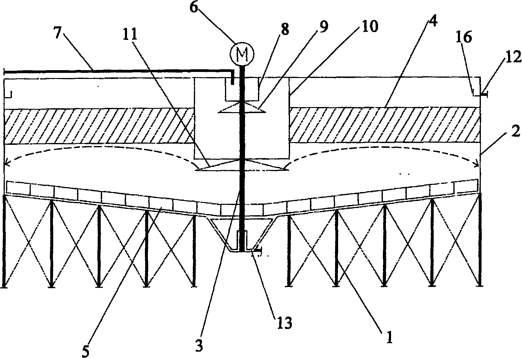
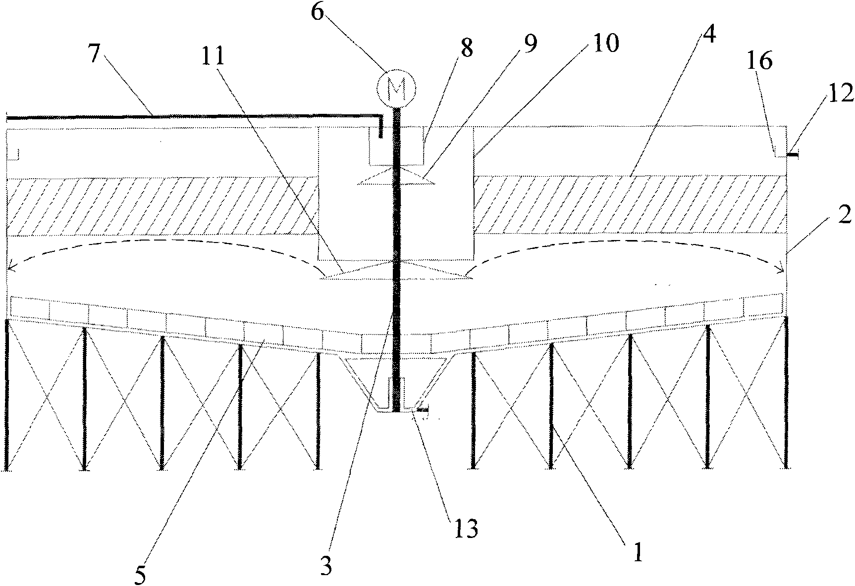
[0015] A clarifier mud scraper, which includes a bracket 1, a cylinder body 2, a diversion device, an inclined plate 4, a mud scraper and a gear motor 6; the diversion device, the inclined plate 4 and the mud scraper are all placed in the cylinder body 2 Inside; cylinder body 2 is installed on bracket 1; the top of cylinder body 2 is provided with gray water inlet 7; the diversion device is two-stage, and the diversion device includes diversion tube and reflection plate; the first-level reflection plate 9 is placed in a Below the first-stage guide tube 8; the first-stage guide tube 8 is placed under the gray water inlet 7 and communicated with the gray water inlet 7; the second-stage guide tube 10 is set on the first-stage guide tube 8 and the first-stage reflector 9 and the outside of the first-level guide tube 8; the second-level reflector 11 is placed below the second-level guide tube 10; the swash plate 4 is placed between the outside of the second-level guide tube 10 and t...

Embodiment 2

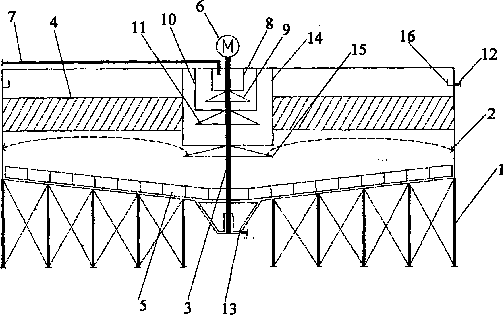
[0024] The difference between this embodiment and Embodiment 1 is that the guide device is three-stage, the three-stage guide tube 14 is set on the outside of the second-stage guide tube 10 and the second-stage reflector 11, and the third-stage reflector 15 is placed on the third Below the first-stage guide tube 14 , the swash plate 4 is placed between the outside of the third-stage guide tube 14 and the side wall of the cylinder body 2 .

[0025] When this embodiment is used, the gray water enters the first-stage diversion tube 8 from the gray water inlet, reflects the water distribution through the first-stage reflector 9 into the second-stage guide tube 10, and then reflects the water distribution through the second-stage reflector 11 to the third stage. In the first-stage guide tube 14, the water is distributed into the cylinder through the reflection of the third-stage reflector 15, and the gray water flow rate of the gray water inlet 7 is just so that the gray water passi...


PUM


Abstract

The invention provides a sludge scraper for a clarifier, which comprises a bracket, a cylinder body, a flow guide device, a sloping plate, a sludge scraping machine and a reducing motor. The sludge water enters a first-stage flow guide cylinder through a sludge water inlet, is reflected and distributed by a first-stage reflecting plate to enter a second-stage flow guide cylinder and then reflected and distributed by a second-stage reflecting plate, and, by the same way, is distributed by a last-stage reflecting plate to enter the cylinder body. The flow velocity of the sludge water at the sludge water inlet is set to allow the sludge water passing through the last-stage reflecting plate to just reach the farthest edge of the cylinder body, so that the degree of turbulence caused by the incoming water is reduced to the lowest. The sloping plate is arranged inside the cylinder body to allow the upward flow to move up along the surface of the sloping plate, so that on the one hand, the sloping plate serves as an extra flow guide device which can reduce the turbulence problem, and on the other hand, the ash settles down on the surface of the sloping plate, which reduces the settlement distance and shortens the clarification time.

Description

technical field [0001] The invention belongs to the technical field of ash water treatment and recycling of a coal chemical gasification furnace, and in particular relates to a recycling device for a high-concentration ash water processor. Background technique [0002] The gasification of coal to obtain clean fuel or other primary chemical products has broad prospects in our country. In order to achieve the goal of energy saving and emission reduction, the gray water produced by the gasifier needs to be recycled. The gray water has high solid content, small particle diameter, high temperature, gray water concentration of more than 3%, and particles with a particle size of 5μ-90μ account for more than 70%, which is more difficult to treat and circulate than conventional muddy water. Because the medium is in a flowing state, and the high temperature makes the surface activity of the medium collect, the turbulent flow phenomenon of the clarifier is very serious. The turbulent ...

Claims


Application Information

Patent Timeline
IPC IPC(8): B01D21/04B01D21/24B01D21/18
Inventor 丁海荣褚士军邹俊峰张综飞
Owner 丁海荣
Why Eureka
Try Eureka