Deburring jig, deburring device and deburring method

A de-flashing and fixture technology, applied in the direction of components with teeth, gear teeth, belts/chains/gears, etc., can solve the problems of increased number of operating procedures, tooth surface damage, and inevitable product quality reduction, etc. The effect of fewer steps

Active Publication Date: 2011-06-29
JATCO LTD
View PDF7 Cites 2 Cited by
  • Summary
  • Abstract
  • Description
  • Claims
  • Application Information

AI Technical Summary

Problems solved by technology

[0009] In any of the above-mentioned methods, along with cutting into the tooth surface of the internal gear, the amount of cutting will vary due to the adjustment amount of the tool or equipment, which may cause damage to the tooth surface
[0010] In addition, depending on the shape of the part, the operation of inserting the cutting tool may be physically difficult, and it may not be suitable for internal gears with a flange on one end surface.
[0011] In addition, in any of the above methods, the control of the deviation is very strict, which inevitably reduces the quality of the product and increases the number of operating procedures, thus leading to an increase in cost

Method used


Image

  • Deburring jig, deburring device and deburring method
  • Deburring jig, deburring device and deburring method
  • Deburring jig, deburring device and deburring method

Examples


Embodiment Construction

[0038] Hereinafter, embodiments of the present invention will be described with reference to the drawings.

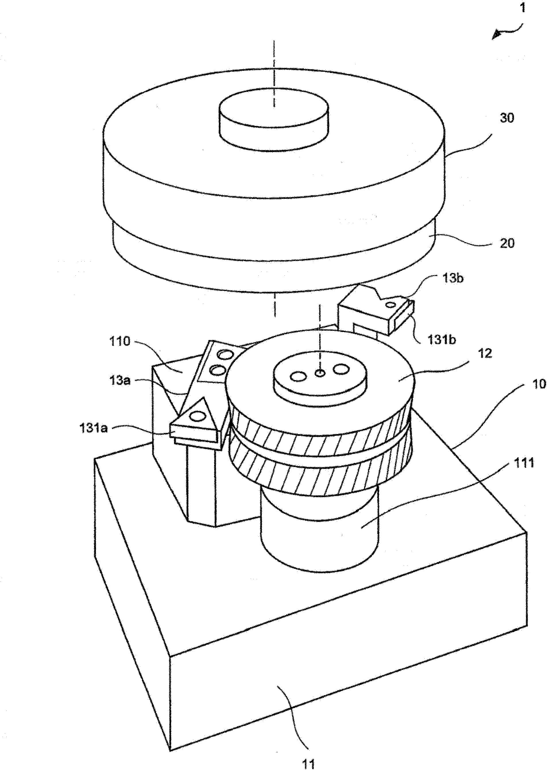
[0039] figure 1 It is an explanatory diagram showing the configuration of the deburring device 1 according to the embodiment of the present invention.

[0040] The deburring device 1 of this embodiment is used to remove Figure 4 A device for forming burrs on the gear end face of the internal gear-shaped workpiece 20 described later.

[0041] The deflashing device 1 is composed of a deflashing jig 10 that removes the burrs of the workpiece 20 , and a rotation device 30 that holds the workpiece 20 and rotates the workpiece 20 .

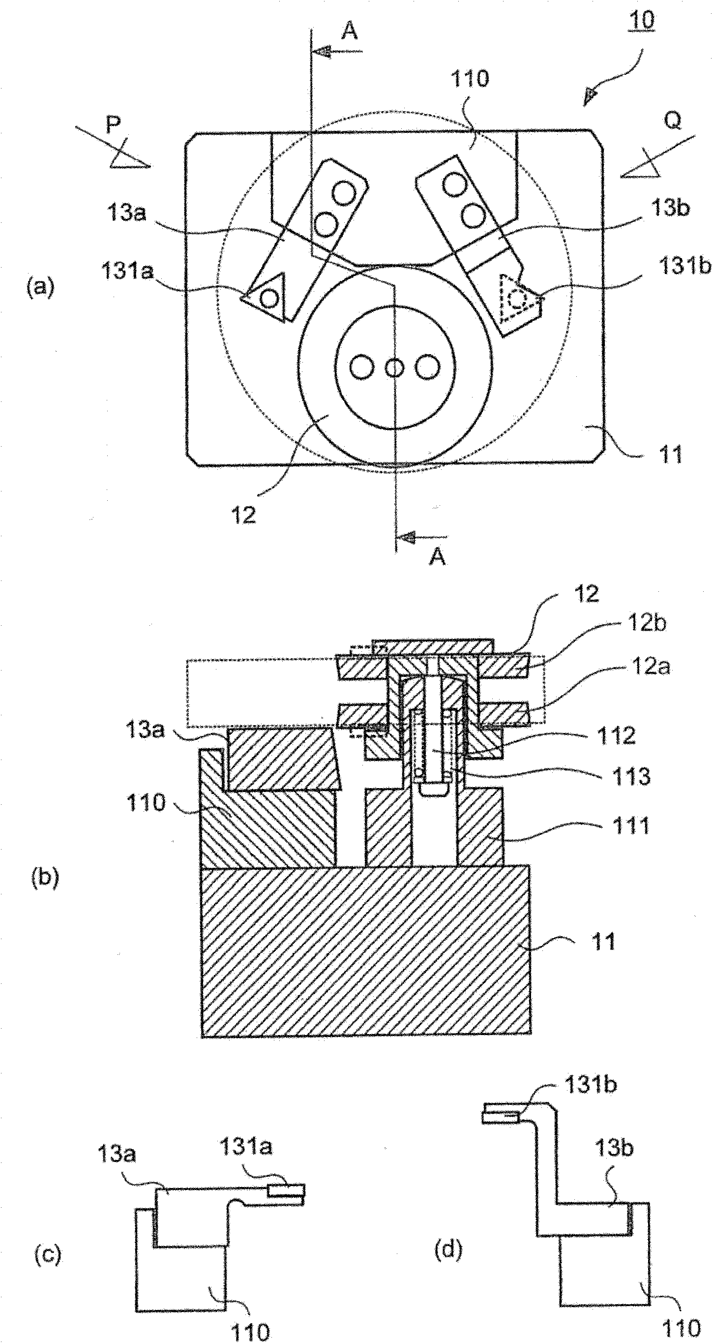
[0042] The deburring fixture 10 is composed of a base 11 , a deburring pressing gear 12 , and a blade holder 13 .

[0043] The base 11 is the base for fixing the deburring pressing gear 12 and the blade holder 13 .

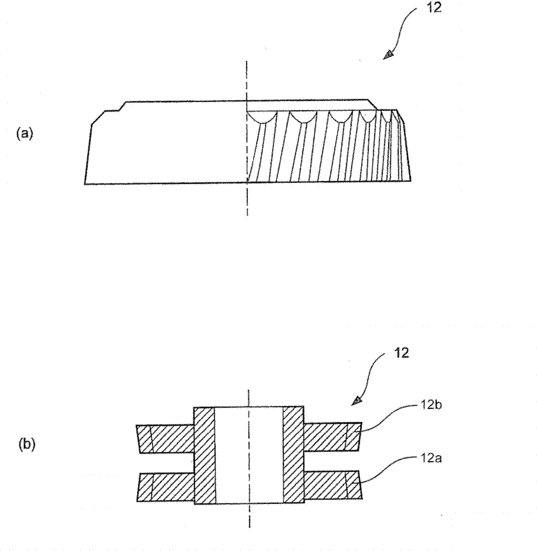
[0044] The deburring pressing gear 12 is a component for extruding flashing from the tooth surface to the end surface of the w...


PUM


Abstract

The invention provides a deburring jig, a deburring device and a deburring method, wherein the fins of workpieces are removed.The deburring device (1) comprises a first blade (131a) and a first gear (12a). One end face of a gear-shaped workpiece (20) is rotated to be cut by the first blade. The rotatably provided first gear is engaged with the edge lines of the gear-shaped face and another edge face of the workpiece (20).The fins on the edge face of the gear of the rotary workpieces are cut off by the first blade (131a).

Description

technical field [0001] The invention relates to a flash removing fixture, a flash removing device and a flash removing method for removing flash formed on workpieces such as gears. Background technique [0002] The gear processing of the internal gear is formed by gear forming, broaching, press processing, etc. After forming, the tooth end surface is subjected to rotary cutting processing. In this forming process and the rotary cutting process, burrs, flying warping, swelling, etc. (hereinafter simply referred to as "burrs") are generated at the ends. [0003] In order to remove such burrs, the following methods are known. [0004] First, there is a method in which an operator manually removes one tooth, one tooth, one end surface, and one end surface with a file, a knife-shaped cutter, or the like. [0005] In addition, there is also a method of mechanically reciprocating a forming tool processed into a tooth groove shape, and performing rotary cutting processing tooth by...

Claims


Application Information

Patent Timeline
IPC IPC(8): B23F19/00
Inventor 松原正己
Owner JATCO LTD
Why Eureka
Try Eureka