Supercharge Your Innovation With Domain-Expert AI Agents!

Fin-and-oval tube heat exchanger

A technology of heat exchangers and round tubes, applied in the field of tube-fin heat exchangers, can solve the problems of large resistance loss and poor heat transfer capacity in the wake area, and achieve the effects of accelerated mutual mixing, simple manufacture, and regular arrangement

Active Publication Date: 2012-08-15
兰州金诺绿色能源动力科技有限责任公司
View PDF2 Cites 0 Cited by
  • Summary
  • Abstract
  • Description
  • Claims
  • Application Information

AI Technical Summary

Problems solved by technology

The outstanding problem is that there is a region with poor heat transfer capacity on the fin surface of the round tube fin heat exchanger, that is, the area in contact with the wake region of the round tube, which is usually called the "heat transfer dead zone", and this Larger drag loss in the wake region

Method used


Image

  • Fin-and-oval tube heat exchanger
  • Fin-and-oval tube heat exchanger
  • Fin-and-oval tube heat exchanger

Examples


Embodiment Construction

[0013] Below in conjunction with accompanying drawing, the present invention is described in further detail:

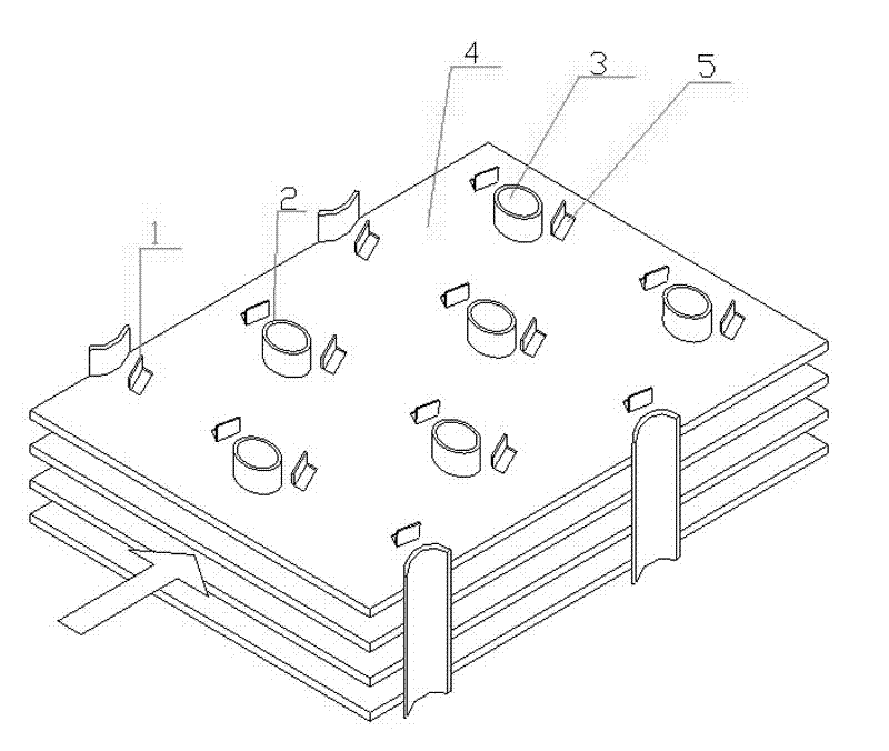
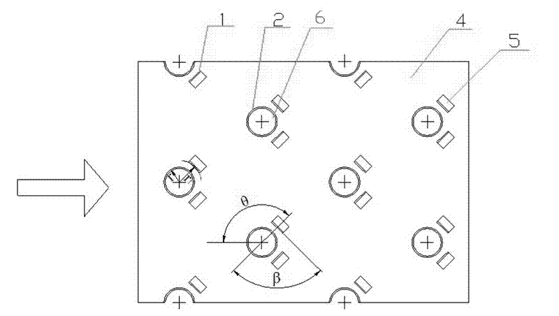
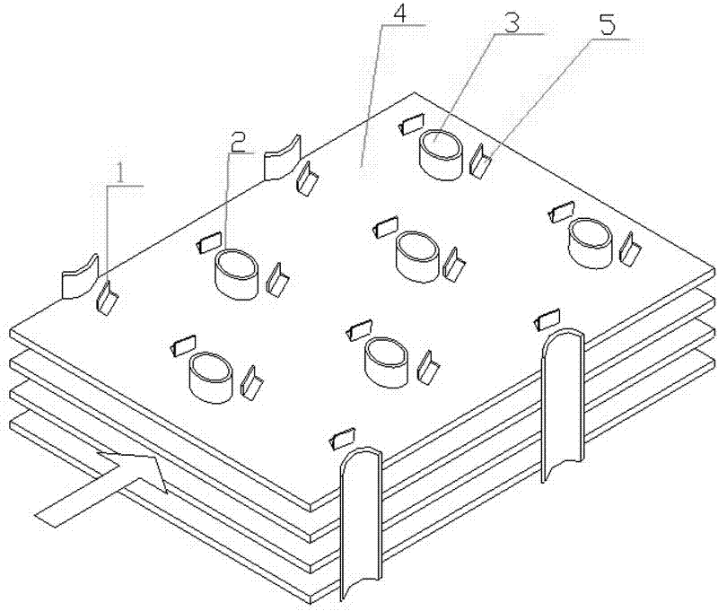
[0014] The invention is a round tube fin heat exchanger, which comprises round tubes 3 arranged along the gas flow direction and fins 4 sleeved on the round tubes 3 . In order to improve the heat exchange performance, the circular tubes 3 are arranged in a forked row. The fins 4 are provided with round holes 6 for fitting round tubes 3, and a pair of rectangular winglet planar vortex generators 1 are punched out at the rear of each round hole 6, and a pair of rectangular small holes are left on the fins 4. 5. The planar vortex generator 1 is perpendicular to the fins 4, the side connecting the planar vortex generator 1 and the fins 4 is the base, and the midpoint of the base is at the intersection of the rear transverse tangent of the circular hole 6 and the tangent on both sides of the circular tube 3 , and the bottom edge is perpendicular to the line connecting th...


PUM


Abstract

The invention provides a fin-and-oval tube heat exchanger, and relates to the technical field of finned heat exchangers. The heat exchanger comprises oval tubes arranged along the gas flowing direction and fins sleeved on the oval tubes, wherein round holes for sleeving the oval tubes are formed on the fins; a flange boss is arranged on the edge of each round hole, and the height of the flange boss equals to the interval between fins; and a pair of rectangular winglet vortex generators which are symmetrically distributed above and under the central line of the round holes are stamped on the rear part of each round hole, and a pair of rectangular pores are reserved on the fin. After the rectangular vortex generators are stamped on the rear flange of the hole for sleeving the oval tube, airflow can generate a vertical vortex through the vortex generators, and causes second flow along a main flow, so that mutual mixing between cold fluid and hot fluid is accelerated. Meantime, the vortex generators change the flowing direction, and a fluid channel reaching the tail part of the oval tube is formed between the oval tube and the vortex generators, so that the return flow zone at the tail part of the oval tube is reduced, the heat exchange performance between the fins at the tail end of the oval tube and fluid is improved, and mechanical energy consumption in a tail flow zone is reduced.

Description

technical field [0001] The invention relates to the technical field of tube-fin heat exchangers, in particular to a circular tube-fin heat exchanger. Background technique [0002] The round tube fin heat exchanger has a wide range of uses, and strengthening the heat transfer performance of the round tube fin heat exchanger can effectively reduce energy consumption and reduce emissions. Installing fins on the tube fin side of the round tube fin heat exchanger to increase the heat transfer area and reduce the thermal resistance on the gas side is an effective measure to improve heat transfer. Due to economical and size constraints, the area of ​​the fins cannot be increased indefinitely. In order to further improve the heat transfer performance of the round tube fin heat exchanger, the fin surface is made into various structures. Such as corrugated fins, slotted fins, louver fins, etc. A more effective way is to punch a vortex generator on the surface of the fin. The existe...

Claims


Application Information

Patent Timeline
Patent Type & Authority Patents(China)
IPC IPC(8): F28F1/32F28F13/12
Inventor 王良璧林志敏常立民王良成武祥董元信苏梅
Owner 兰州金诺绿色能源动力科技有限责任公司
Features
  • R&D
  • Intellectual Property
  • Life Sciences
  • Materials
  • Tech Scout
  • Unparalleled Data Quality
  • Higher Quality Content
  • 60% Fewer Hallucinations
Learn More