Thermal exhaust air treatment plant

A waste gas purification and thermal technology, applied in lighting and heating equipment, incinerators, combustion types, etc., can solve problems such as reducing the residence time of split flow, and achieve the effect of improving flow resistance and good distribution

Active Publication Date: 2012-11-28
杜尔涂装系统工程(上海)有限公司
View PDF3 Cites 1 Cited by
  • Summary
  • Abstract
  • Description
  • Claims
  • Application Information

AI Technical Summary

Problems solved by technology

However, a disadvantage of this deflection chamber is that this design of the deflection chamber results in a reduced residence time for the partial flow that is not removed via the hot gas bypass valve.

Method used


Image

  • Thermal exhaust air treatment plant
  • Thermal exhaust air treatment plant
  • Thermal exhaust air treatment plant

Examples


Embodiment Construction

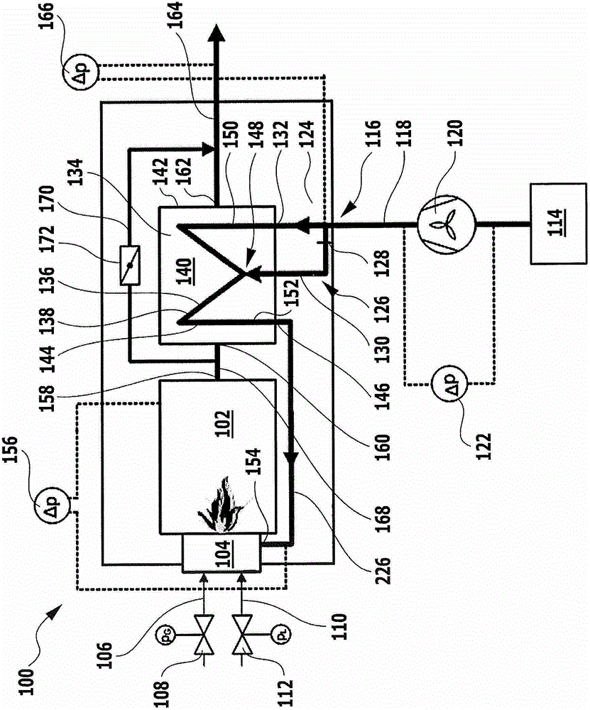
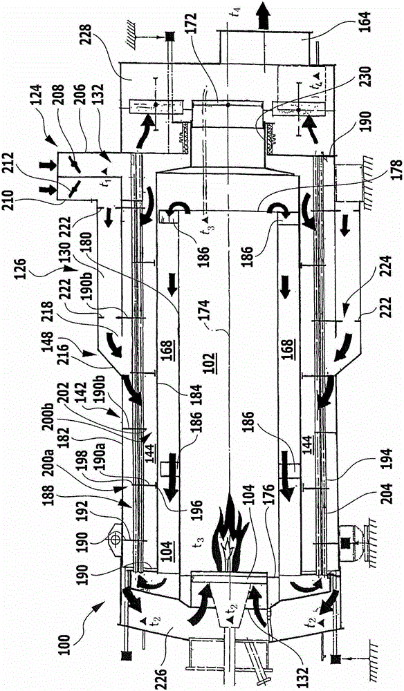
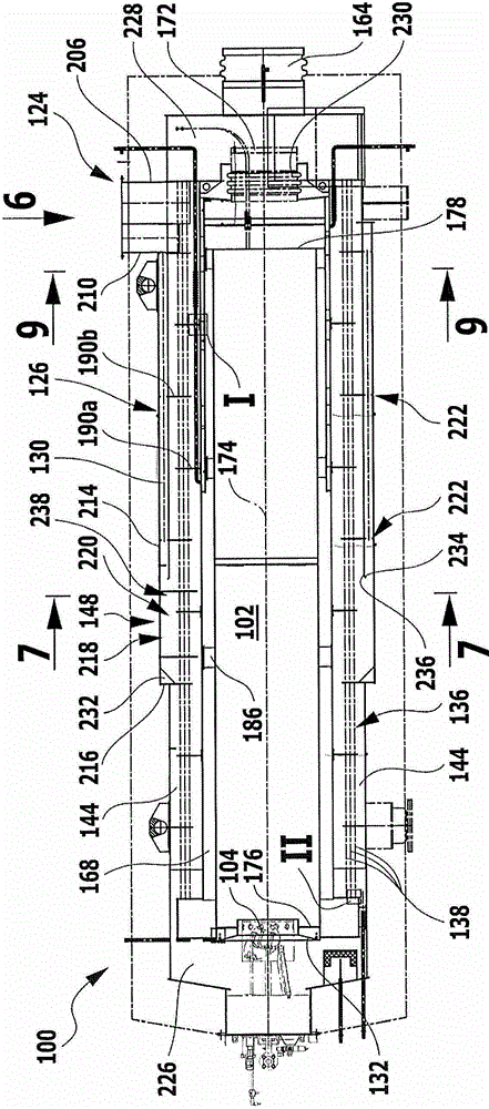
[0087] exist figure 1 with figure 2 The thermal exhaust gas purification plant shown in , denoted as a whole by the reference number 100 , as shown by figure 1 As can be seen from the schematic schematic diagram of the combustion chamber, it includes a combustion chamber 102, a burner 104 is arranged on the combustion chamber inlet of the combustion chamber, and suitable fuel, such as natural gas, can be delivered to the burner through a fuel pipeline 106 with a fuel valve 108, As well as cooling air for the ignition electrode, sight glass and flame monitoring can then be supplied to the burner via a cooling air line 110 with a cooling air valve 112 .

[0088] The exhaust gas to be cleaned is a gas mixture which contains oxidizable components such as volatile organic compounds.

[0089] The oxidizable components of the exhaust gas are oxidized in the combustion chamber 102 together with the added fuel and rendered harmless.

[0090] The mixed gas containing combustible com...


PUM


Abstract

To provide a thermal exhaust air treatment plant, comprising a combustion chamber and a heat exchanger for transferring heat from a cleaned gas produced in the combustion chamber to an untreated gas to be supplied to the combustion chamber, wherein the heat exchanger comprises an inner heat exchanger chamber through which an inner fluid medium can flow and comprises an outer heat exchanger chamber through which an outer fluid medium can flow, which thermal exhaust air treatment plant permits regulation of the cleaned gas outlet temperature without a reduction in the cleaned gas quality, it is proposed that the thermal exhaust air treatment plant comprises a bypass device with a separating device by means of which a part of the outer fluid flow can be separated, as a bypass fluid flow, from an outer residual fluid flow, and with an admixing device by means of which the bypass fluid flow can be admixed to the residual fluid flow again after the residual fluid flow has passed through a section of the outer heat exchanger chamber.

Description

technical field [0001] The invention relates to a thermal exhaust gas purification plant comprising a combustion chamber and a heat exchanger for transferring heat from the clean gas produced in the combustion chamber to the raw gas to be fed to the combustion chamber, wherein the heat exchanger The heat exchanger comprises an inner heat exchanger space through which an inner fluid medium can flow and an outer heat exchanger space through which an outer fluid medium can flow. Background technique [0002] The net gas discharged from such a thermal exhaust gas purification system is usually used for other thermodynamic processes, so that the net gas discharge temperature must be adjusted when discharging from the thermal exhaust gas purification system. [0003] In order to regulate the net gas discharge temperature, an internal hot gas bypass valve is used according to the prior art. By opening or partially opening this valve, the very hot clean gas is guided directly from ...

Claims


Application Information

Patent Timeline
Patent Type & Authority Applications(China)
IPC IPC(8): F23G7/06
CPCF23G5/50F23G7/066
Inventor 托尔斯滕·吉辛埃哈德·里德
Owner 杜尔涂装系统工程(上海)有限公司
Why Eureka
Try Eureka