Laser gyro combined offset frequency method and combined device for inertial measurement of laser gyro

A laser gyro and frequency bias technology, which is applied in the improvement field of laser gyro frequency bias technology, can solve problems such as inability to work continuously without interruption, and achieve the effects of improving accuracy, reducing power reserve requirements, and being easy to implement

Active Publication Date: 2011-06-29
SHAANXI BAOCHENG AVIATION INSTR
View PDF4 Cites 6 Cited by
  • Summary
  • Abstract
  • Description
  • Claims
  • Application Information

AI Technical Summary

Problems solved by technology

But it doesn't work continuously without interruption
[0003] Although the "two-way constant speed and mechanical jitter combined frequency bias method" of the laser gyroscope cannot completely eliminate the influence of

Method used


Image

  • Laser gyro combined offset frequency method and combined device for inertial measurement of laser gyro
  • Laser gyro combined offset frequency method and combined device for inertial measurement of laser gyro
  • Laser gyro combined offset frequency method and combined device for inertial measurement of laser gyro

Examples


Embodiment Construction

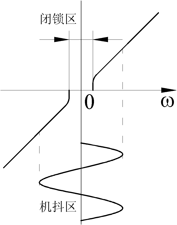
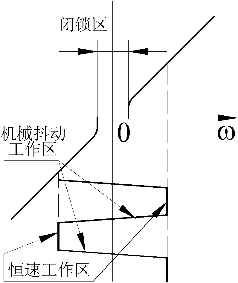
[0028] Take the three-axis laser gyro group as an example. Specifically (taking the three-axis laser gyro as an example), the present invention is realized according to the following steps:

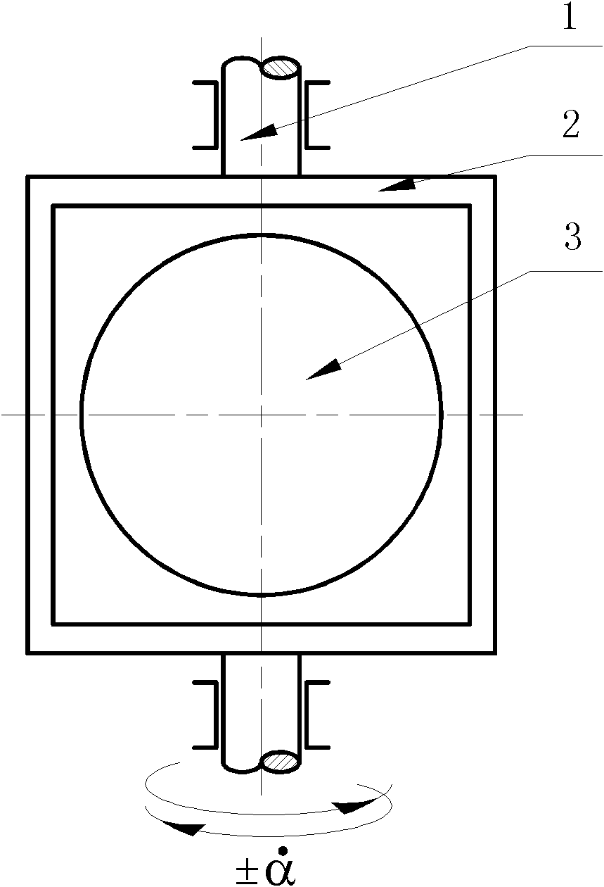
[0029] 1. (see image 3 ) on the bidirectional constant-speed bias turntable (2) rotating around the vertical axis (1), install the three-axis laser gyro group (3), and the three sensitive axes of the three-axis laser gyro group (3) (which are mutually orthogonal ) are deviated from the rotation axis (1) β (54.7356°) angle of the frequency deviation turntable.

[0030] 2. The two-way constant-speed bias-frequency turntable (2) is driven by a synchronous motor with a gear reducer. On the turntable (see Figure 4 ) Use a boss (4) and a lever (5) installed on the base and a photoelectric switch (6) to control the steering of the synchronous motor, and the limit pin (7) that limits the movement of the lever is also used as the limit pin of the turntable , the rotation angle of the turntabl...


PUM


Abstract

The invention provides a laser gyro combined offset frequency method, belonging to the technical field of inertial navigation equipment. The method comprises the following steps: combination with two-way constant speed and mechanical shaking is adopted; a 1-3 axis laser gyro group is arranged on a two-way constant-speed offset-frequency rotary platform rotating around a vertical axis, all sensitive axes of the laser gyro are deviated from a beta angle of a rotary axis of the offset-frequency rotary platform and are driven by the rotary platform to rotate, and a component (alpha & cosine beta)of the rotary angle speed (alpha &) on all the sensitive axes of the laser gyro is the offset-frequency angle speed of the laser gyro; and simultaneously, the rotary angle speed (alpha &) carries outrotary modulation on the error of the laser gyro axis. In the laser gyro combined offset frequency method adopting combination of two-way constant speed offset frequency and mechanical shaking offsetfrequency, not only is the accuracy guaranteed, but also the difficulties for design and manufacture are reduced. The laser gyro combined offset frequency method can be used for high-accuracy laser gyro strapdown inertial systems.

Description

technical field [0001] The invention belongs to the technical field of inertial navigation equipment, in particular to the improvement of laser gyro frequency bias technology. Background technique [0002] There are many kinds of frequency biasing technologies for laser gyroscopes to solve the influence of laser gyroscope locking effect. The mechanical jitter frequency bias technology is the most widely used, while the rate frequency bias technology achieves the highest accuracy. However, neither of these two frequency bias techniques can completely eliminate the influence of the "lock-in" effect, and the over-lock zone error is still the main source of error. Only the bidirectional constant speed bias technology used in the invention patent "Bidirectional constant speed bias laser gyro north finding method and bidirectional constant speed bias laser gyro north finder" with the patent publication number of CN 101738182A can completely eliminate the "locking" effect Impact....

Claims


Application Information

Patent Timeline
IPC IPC(8): G01C19/64G01C21/18
Inventor 赵永康陈磊江谢玲陈家斌黄凯赵治伟马英华
Owner SHAANXI BAOCHENG AVIATION INSTR
Why Eureka
Try Eureka