Controlling memory redundancy in a system

A technology of memory and memory nodes, the redundancy in hardware is used for data error detection, instrumentation, and response error generation, etc., which can solve problems such as uncorrectable master nodes and system crashes.

Active Publication Date: 2011-06-29
INTEL CORP
View PDF2 Cites 11 Cited by
  • Summary
  • Abstract
  • Description
  • Claims
  • Application Information

AI Technical Summary

Problems solved by technology

There is a reasonable possibility that a master node that has experienced some correctable error that caused the migrat

Method used


Image

  • Controlling memory redundancy in a system
  • Controlling memory redundancy in a system
  • Controlling memory redundancy in a system

Examples


Embodiment Construction

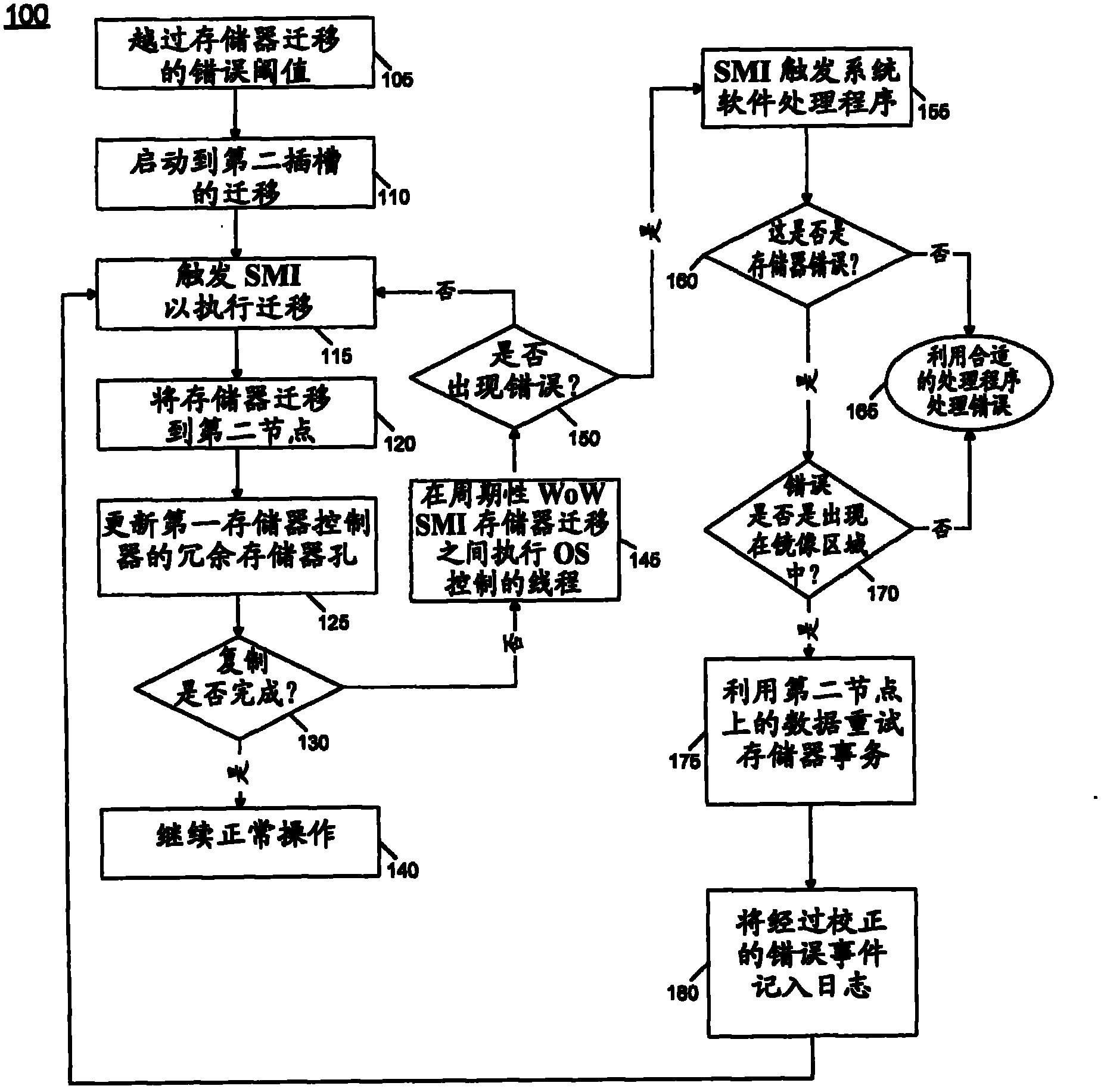
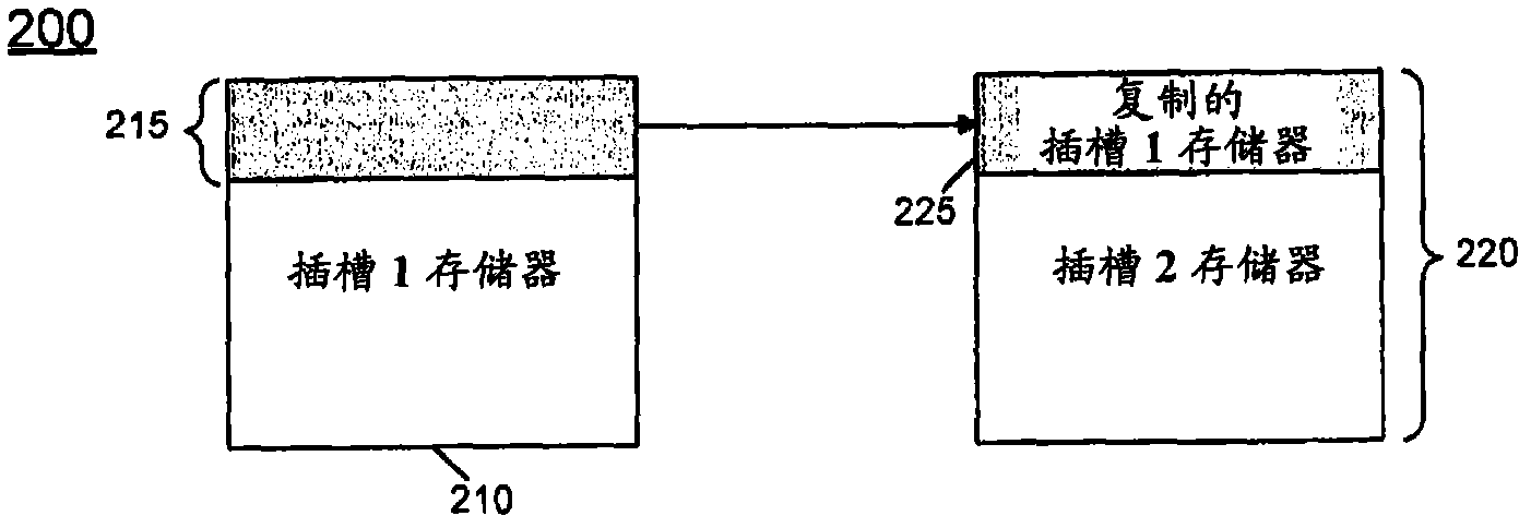
[0025] In various embodiments, during a migration operation, management software (e.g., Basic Input Output System (BIOS)) may interact with system hardware so that uncorrectable errors are encountered at the primary node during the memory migration process while in migration mode This enables the slave memory node to process the access request. During memory migration, the BIOS can read the cache line (filled by the master) and write it back (to the master and slave). In this way, the contents of the master node can eventually be copied to the slave nodes on a cache-line by cache-line basis. This is called write-on-write (WOW) replication. Note that write-on-read (WOR) is handled in a similar fashion, but these writes are done by the hardware itself after the BIOS reads the cache line. During migration, as the management software starts copying storage, it can disambiguate ranges of storage that have been copied (and are now redundant) from ranges that are yet to be copied (...


PUM


Abstract

In one embodiment, the present invention provides an ability to handle an error occurring during a memory migration operation in a high availability system. In addition, a method can be used to dynamically remap a memory page stored in a non-mirrored memory region of memory to a mirrored memory region. This dynamic remapping may be responsive to a determination that the memory page has been accessed more than a threshold number of times, indicating a criticality of information on the page. Other embodiments are described and claimed.

Description

technical field [0001] The present invention relates to controlling memory redundancy in a system. Background technique [0002] In today's ubiquitous server world, maintaining good server reliability and uptime is almost mandatory. To maintain critical system uptime, system designers build in reliability, availability, serverability, manageability (RASM) characteristics to improve overall system reliability and availability. Therefore, it is common to find various degrees of redundancy, error correction, error detection and error containment techniques employed at different levels in the system hierarchy. One of the most common types of system failures is attributed to system memory errors. Accordingly, memory subsystems, particularly dual inline memory modules (DIMMs), have received particular attention in this regard. [0003] Although modern memories employ error-correcting codes (ECC) to detect and / or correct single and double-bit errors, high-order multi-bit errors ...

Claims


Application Information

Patent Timeline
IPC IPC(8): G06F11/20
CPCG06F11/1666G06F11/20G06F11/203
Inventor R·C·斯旺森M·S·纳图R·卡纳M·K·纳奇穆图S·贾亚库马尔A·S·克沙夫阿穆蒂N·兰加纳萨恩
Owner INTEL CORP
Why Eureka
Try Eureka