Oil shielding device for evaporation

An oil shielding and oil-gas technology, which is applied in vacuum evaporation plating, sputtering plating, ion implantation plating, etc., can solve the problems of uncontrolled oil flow, high use cost, and rapid oil aging, and achieve cost reduction, Aging time becomes longer and the effect of improving product quality

Inactive Publication Date: 2011-06-29
TONGLING DONGSHI ELECTRONICS
View PDF0 Cites 5 Cited by
  • Summary
  • Abstract
  • Description
  • Claims
  • Application Information

AI Technical Summary

Problems solved by technology

[0003] The purpose of the present invention is to solve the problems of rapid oil aging, high use cost, uncontrolled oil flow and affecting product quality in the existing oil shielding device

Method used


Image

  • Oil shielding device for evaporation
  • Oil shielding device for evaporation
  • Oil shielding device for evaporation

Examples


Embodiment Construction

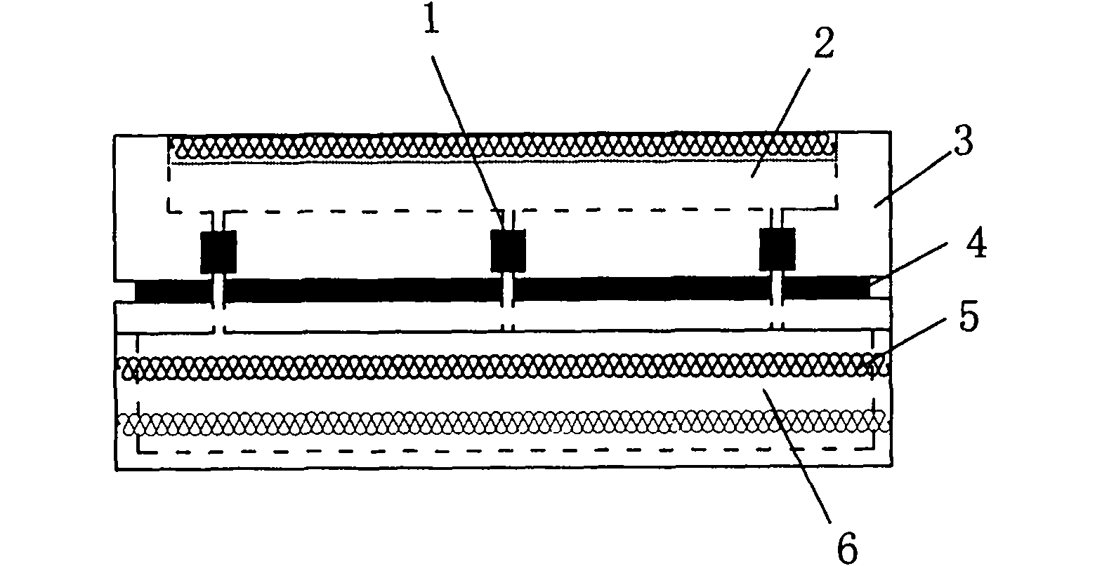
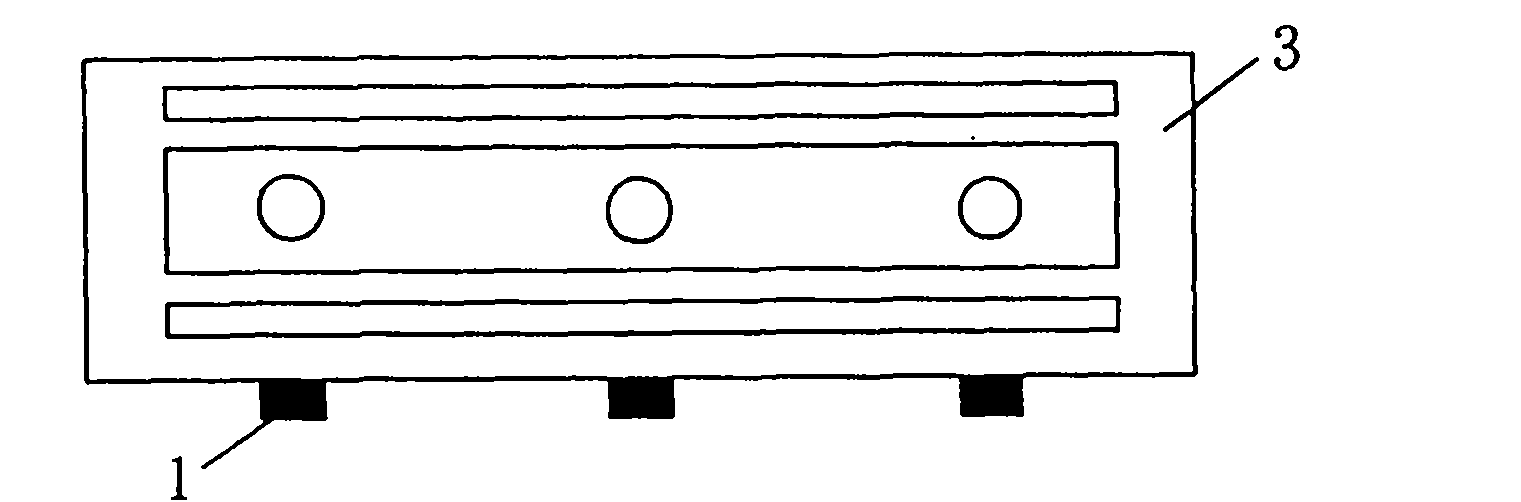
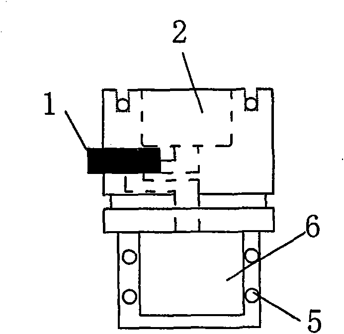
[0012] An oil shielding device for vapor deposition of the present invention, such as figure 1 , figure 2 , image 3 As shown, it includes an oil-gas tank 3 divided into an upper chamber 2 and a lower chamber 6, a solenoid valve 1 connecting the upper chamber 2 and the lower chamber 6, and a heat pipe 5 for heating the upper chamber 2 and the lower chamber 3 respectively, and the oil-gas tank 3 It is filled with oil, and a heat insulating board 4 is provided between the upper chamber 2 and the lower chamber 6 . The heating pipe 5 for heating the lower chamber 6 is located outside the lower chamber 6 and indirectly heats the oil in the lower chamber 6 . There are three solenoid valves 1, which are evenly distributed on the two ends and the center of the outer wall of the oil-gas tank 3.


PUM


Abstract

The invention provides an oil shielding device for evaporation. The device comprises an oil gas groove [3] divided into an upper chamber [2] and a lower chamber [6], solenoid valves connecting the upper chamber [2] and the lower chamber [6] and a heating pipe [5] heating the upper chamber [2] and the lower chamber [6] respectively, wherein the oil gas groove [3] is filled with oil; and the heating pipe [5] heating the lower chamber [6] is arranged outside the lower chamber [6] and heats the oil in the lower chamber [6] indirectly. The structure has the beneficial effects of greatly lowering the use cost and improving the product quality.

Description

technical field [0001] The invention relates to an oil shielding device for vapor deposition of capacitor metallized film. Background technique [0002] In the production of capacitor metallized film coating, the oil shielding device adopted includes an oil-gas tank divided into an upper chamber and a lower chamber, a solenoid valve connecting the upper chamber and the lower chamber, and heating pipes for heating the upper chamber and the lower chamber respectively. It is divided into upper and lower chambers to be heated separately. The heating of the lower chamber mainly depends on the direct heating of the heat pipe placed in the oil in the lower chamber. Oil, the two solenoids cannot be controlled individually in use. There are mainly the following problems in use: 1. Because the lower chamber adopts the direct heating method of the heat pipe, the shielding oil ages quickly, resulting in increased evaporation costs. 2. The oil flow control at both ends is adopted, so th...

Claims


Application Information

Patent Timeline
Patent Type & Authority Applications(China)
IPC IPC(8): H01G13/00C23C14/24
Inventor 佘强钱加圣
Owner TONGLING DONGSHI ELECTRONICS
Why Eureka
Try Eureka