Photomultiplier installation protection structure

A technology for photomultiplier tubes and protective structures, which is applied in the directions of electron multiplier tubes, detailed information of electron multipliers, discharge tubes, etc., can solve the problems of photomultiplier tubes being easily damaged by vibration, inconvenient to operate photomultiplier tubes, and less research on installation and protection.

Inactive Publication Date: 2011-06-29
THE THIRD RES INST OF MIN OF PUBLIC SECURITY
View PDF2 Cites 7 Cited by
  • Summary
  • Abstract
  • Description
  • Claims
  • Application Information

AI Technical Summary

Problems solved by technology

[0009] The technical problem to be solved by the present invention is that the photomultiplier tube is easily damaged by vibration and cannot be irradiated by strong light, and in the prior art, there are too many researches on the performance of the photomultiplier tube, and less research on installation protection, and the installation protection effect is not good. Inconvenient to operate and installation protection is very important to the use of photomultiplier tubes, so a kind of installation and protection structure of photomultiplier tubes is proposed. This structure can well protect the photomultiplier tubes from being damaged by vibration and also It will not be affected by strong light, and it will not affect the installation at the same time. It is very convenient to install

Method used


Image

  • Photomultiplier installation protection structure
  • Photomultiplier installation protection structure
  • Photomultiplier installation protection structure

Examples


Embodiment Construction

[0034] In order to make the technical means, creative features, goals and effects achieved by the present invention easy to understand, the present invention will be further described below in conjunction with specific illustrations.

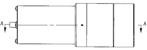
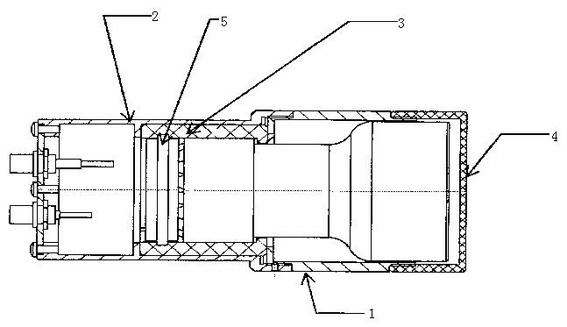
[0035] The installation and protection structure of the entire photomultiplier tube is shown in the attached figure 1 And attached figure 2 , The installation protection structure includes an upper shell 1, a lower shell 2, a silicon rubber ferrule 3, and a protective cover 4.

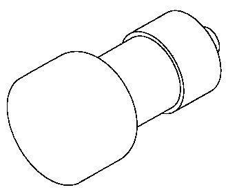
[0036] The structure of the photomultiplier tube is attached image 3 .

[0037] The shape and structure of the silicone rubber ferrule 3 are shown in the attached Figure 4 , attached Figure 5 , attached Figure 6 , the silicone rubber ferrule 3 is designed as a cylindrical cavity with a slot 31 and a positioning slot 32 for protecting and limiting the photomultiplier tube. In order to facilitate placement, a through slot 33 is opened on the upper side of the pro...


PUM


Abstract

The invention discloses a photomultiplier installation protection structure. The structure has the following beneficial effects: a rubber clamp sleeve is sleeved on a tail tube of a photomultiplier, and a metal shell is added to the outside the rubber clamp sleeve to apply certain pre-tightening force to the rubber clamp sleeve, so that the photomultiplier can be tightly wrapped up and can not radially drift; a clamp slot is arranged in the rubber clamp sleeve and a ceramic substrate of the photomultiplier is clamped in the clamp slot, thus solving the problem of axial drifting of the photomultiplier; therefore, the photomultiplier is hard to damage due to vibration; besides, the whole photomultiplier is hermetically put in the metal shell, thus avoiding the possible impact of hard light irradiation on the photomultiplier; in terms of installation, a through slot is arranged at one side of the rubber clamp sleeve and a slot with middle parts connected is arranged at the opposite side of the rubber clamp sleeve, so that the two parts of the clamp sleeve are incompletely disconnected, when the photomultiplier is put in the clamp sleeve, the two parts of the clamp sleeve are disconnected along the through slot and the tail tube of the photomultiplier is put in the inner cavity of the clamp sleeve, and the operations are very convenient; and the structure is simple and packaging process is simple and convenient, effects are good.

Description

technical field [0001] The invention relates to the field of detection devices of X imaging systems, in particular to a photomultiplier tube installation protection structure. Background technique [0002] A photomultiplier tube is a vacuum device, which consists of a photoemission cathode (photocathode), a focusing electrode, an electron multiplier, and an electron collector (anode). Typical photomultiplier tubes can be divided into two types: end window type and side window type according to the receiving mode of the incident light pole. The end-window photomultiplier tube is relatively efficient. Its main working process is as follows: [0003] When light hits the photocathode, the photocathode excites photoelectrons into the vacuum. These photoelectrons enter the multiplication system according to the focusing electric field, and are multiplied and amplified through further secondary emission. The amplified electrons are collected by the electron collector as a signa...

Claims


Application Information

Patent Timeline
Patent Type & Authority Applications(China)
IPC IPC(8): H01J43/04H01J43/28
Inventor 温亚珍尤晓明丁志平
Owner THE THIRD RES INST OF MIN OF PUBLIC SECURITY
Why Eureka
Try Eureka