Anti-drifting device for differential heat treatment, differential temperature furnace and differential heat treatment method

A technology of differential temperature heat treatment and anti-channeling, which is applied in the field of heat treatment and can solve problems such as poor hardness uniformity and manufacturing difficulties

Active Publication Date: 2021-04-30
TIANJIN HEAVY EQUIP ENG RES +1
View PDF3 Cites 0 Cited by
  • Summary
  • Abstract
  • Description
  • Claims
  • Application Information

AI Technical Summary

Problems solved by technology

[0004] In view of the above analysis, the present invention aims to provide a differential temperature heat treatment anti-channeling device, a differential temperature furnace and a differential temperature heat treatment method to solve the problems of difficulty in manufacturing work rolls and poor uniformity of hardness in aluminum plate rolling mills in the prior art

Method used


Image

  • Anti-drifting device for differential heat treatment, differential temperature furnace and differential heat treatment method
  • Anti-drifting device for differential heat treatment, differential temperature furnace and differential heat treatment method
  • Anti-drifting device for differential heat treatment, differential temperature furnace and differential heat treatment method

Examples


Embodiment 1

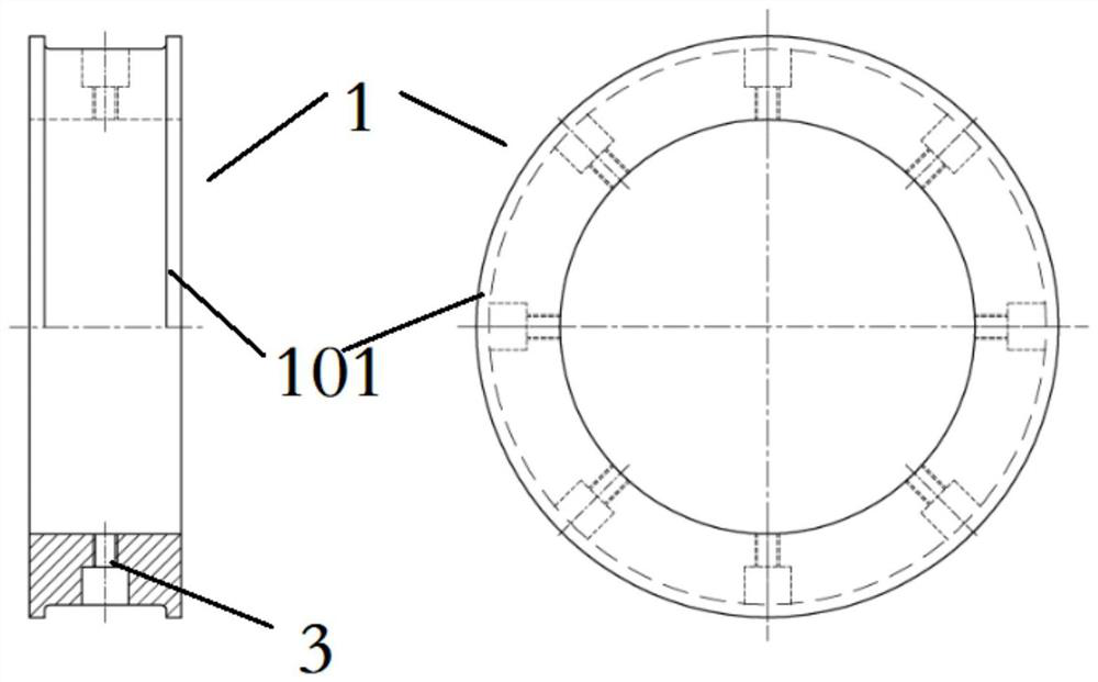
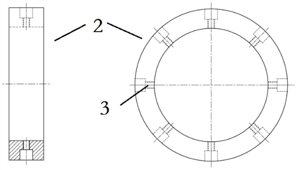
[0072] An anti-channeling device for differential temperature heat treatment of work rolls of an aluminum plate rolling mill, comprising an anti-channeling sleeve and a support sleeve, both of which are hollow cylindrical structures, and ring-shaped anti-channeling protrusions are arranged at both ends of the anti-channeling sleeve.

[0073] Both the anti-channeling sleeve and the supporting sleeve are uniformly provided with 8 threaded holes in the circumferential direction, and the anti-channeling sleeve and the supporting sleeve are fixed on the roll necks at both ends through the threaded holes with hexagon socket head screws.

[0074] The anti-channeling sleeve and the support sleeve have the same inner diameter and outer diameter. In this embodiment, the inner diameter outer diameter The axial length of the supporting wheel is 155mm, the axial length of the anti-channeling sleeve is 300mm, the height of the anti-channeling protrusion is 25mm, the width of the anti-chan...

Embodiment 2

[0076] A differential temperature heat treatment method for work rolls of an aluminum plate rolling mill. In this embodiment, the dimensions and main technical requirements of the work rolls are:

[0077] Table 1 Work roll size and hardness requirements

[0078]

[0079] Table 2 Main chemical composition of work rolls in this example (wt.%)

[0080] C Si mn Cr Ni Mo V Fe 0.30-0.70 0.40-0.80 0.40-0.80 4.50-5.50 0.20-0.80 0.40-0.80 0.10-0.50 the remaining

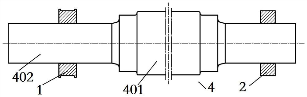
[0081] Step 1. Adjust the positions of the two ends of the horizontal open and close furnace body according to the length of the work roll rough machining roll body of 3975 mm.

[0082] Step 2. Install the anti-channeling sleeve and the support sleeve symmetrically on the small roll necks at both ends of the work roll. The distance between the two is 6000mm, and they are fastened with hexagon socket head screws, such as Figure 5 shown. It should be noted here that the height of the ...


PUM

PropertyMeasurementUnit
lengthaaaaaaaaaa

Abstract

The invention discloses an anti-channeling device for differential heat treatment, a differential temperature furnace and a differential heat treatment method, belongs to the technical field of heat treatment, and solves the problems of difficulty in manufacturing a working roll of an aluminum plate rolling mill, poor hardness uniformity and the like in the prior art. The anti-drifting device for differential heat treatment comprises an anti-drifting sleeve and a supporting sleeve, wherein the anti-channeling sleeve and the supporting sleeve are each of a hollow cylindrical structure; the anti-channeling sleeve and the supporting sleeve are separately used for being arranged on roller necks at two ends of the working roll in a sleeving manner; and annular anti-drifting bulges are arranged at two ends of the anti-drifting sleeve and used for preventing the working roll from shifting in the axial direction in the rotating process. The device and the method are suitable for differential heat treatment of the working roll of the aluminum plate rolling mill.

Description

technical field [0001] The invention belongs to the technical field of heat treatment, in particular to a differential temperature heat treatment anti-channeling device, a differential temperature furnace and a differential temperature heat treatment method. Background technique [0002] In recent years, with the promotion of lightweight automobiles, the development of rail transit, the popularization of high-performance aluminum profiles for doors and windows and all-aluminum homes, the market demand for high-end aluminum profiles has increased. The work rolls of the aluminum plate rolling mill are the key components in the aluminum plate hot rolling mill. High quality and large size are the higher requirements of the market. [0003] Due to the large size, high technical requirements and large length-to-diameter ratio of the work rolls of aluminum plate rolling mills, their manufacture is extremely difficult. The traditional power frequency induction hardening method canno...

Claims


Application Information

Patent Timeline
Patent Type & Authority Applications(China)
IPC IPC(8): C21D9/38C21D1/18C21D1/06
CPCC21D9/38C21D9/0025C21D1/18C21D1/06
Inventor 王大鹏南玉静郭峰赵席春
Owner TIANJIN HEAVY EQUIP ENG RES
Why Eureka
Try Eureka