
Self-expanded stent

A self-expanding, stent rod technology, applied in the field of medical devices, can solve the problems of tissue hyperplasia, uneven support force of self-expanding stents, restenosis, etc.

Inactive Publication Date: 2011-07-06
SHANGHAI MICROPORT MEDICAL (GROUP) CO LTD
View PDF5 Cites 2 Cited by
  • Summary
  • Abstract
  • Description
  • Claims
  • Application Information

AI Technical Summary

Problems solved by technology

[0005] In view of this, the present invention provides a self-expanding stent to solve the problem of uneven support force of the ring-designed self-expanding stent, and avoid tissue hyperplasia and restenosis after implantation

Method used


Image

  • Self-expanded stent
  • Self-expanded stent
  • Self-expanded stent

Examples


Embodiment Construction

[0037] The invention discloses a self-expanding stent to solve the problem of uneven supporting force of the ring-designed self-expanding stent and avoid tissue hyperplasia and restenosis after implantation.

[0038] The following will clearly and completely describe the technical solutions in the embodiments of the present invention with reference to the accompanying drawings in the embodiments of the present invention. Obviously, the described embodiments are only some, not all, embodiments of the present invention. Based on the embodiments of the present invention, all other embodiments obtained by persons of ordinary skill in the art without making creative efforts belong to the protection scope of the present invention.

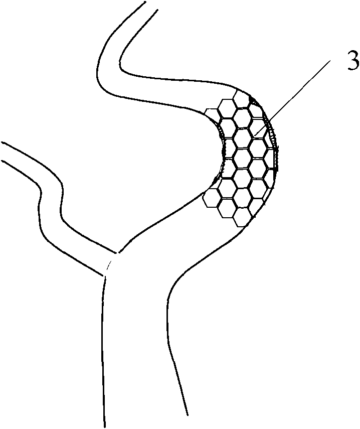
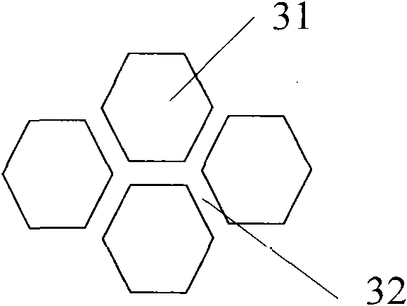
[0039] see figure 2 , image 3 , figure 2 A schematic diagram of implanting a self-expanding stent into a cerebral artery provided by an embodiment of the present invention, image 3 Partial enlarged view of the self-expanding stent provided by the ...


PUM


Abstract

The embodiment of the invention discloses a self-expanded stent which has a hollow tubular meshed structure; stent rod pieces are arranged at the periphery of a mesh; and every two adjacent stent rod pieces can form a closed mesh. In the embodiment of the invention, the cerebrovascular stent is in the hollow tubular type, has the uniform mesh structure and is conveyed to the cerebrovascular disease position, the narrow disease position is released through a conveying rod to be expanded so that a blood vessel flowing channel is rebuilt; as the structural design has the uniform continuous closed mesh structure, every two adjacent rod pieces can form the closed mesh to cover stenosis plaque uniformly and continuously so as to provide uniform annular supporting force, and particularly at the bent blood vessel, the rod pieces can be closed to form a continuous lumen channel.

Description

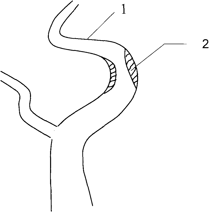
technical field [0001] The invention relates to the technical field of medical devices, and more specifically, to a self-expanding stent. Background technique [0002] Intracranial atherosclerotic stenosis is an important cause of ischemic stroke. In my country, up to 33% of strokes are caused by it, and more than 50% of transient ischemia (TIA) are related to it. Such as figure 1 As shown, wherein 1 is a cerebral artery, and 2 is a cerebral artery stenotic plaque, because cerebral artery 1 produces a lesion of cerebral artery stenotic plaque 2, which can easily lead to transient cerebral ischemia (TIA) and death. Intracranial arterial stenosis mainly occurs at the major arterial bifurcations, such as the origin and siphon of the internal carotid artery, the trunk of the middle cerebral artery, the basilar artery, the origin of the vertebral artery, and the cranial entry. [0003] Cerebral artery stenosis has always been a difficult point in clinical treatment. The study ...

Claims


Application Information

Patent Timeline
Patent Type & Authority Applications(China)
IPC IPC(8): A61F2/90A61F2/92A61M31/00A61L31/02A61L31/16A61L31/14A61F2/91
CPCA61F2/91A61F2250/0067
Inventor 罗七一李雨谢志永金巧蓉王森
Owner SHANGHAI MICROPORT MEDICAL (GROUP) CO LTD
Learn More