Accelerator control system of mini-tiller

A technology of throttle control and micro-tiller, which is applied in the field of micro-tiller, can solve the problems that the adjustment handle is not well positioned, the limit is not obtained, and the controllability of the micro-tiller is poor, so as to achieve simple connection and Reliable, low manufacturing cost, simple and novel structure

Inactive Publication Date: 2011-07-06
周树明 +1
View PDF5 Cites 3 Cited by
  • Summary
  • Abstract
  • Description
  • Claims
  • Application Information

AI Technical Summary

Problems solved by technology

At present, most micro tillage machines realize walking and parking by installing a throttle control device on the micro tiller. This kind of throttle control device mainly includes a mounting seat, a positioning plate is arranged on the mounting seat, and a limit position is set above the positioning plate. The mounting seat, the positioning plate and the limiting plate are fixed through the same adjusting bolt, and an adjusting handle is installed between the positioning plate and the limiting plate, and the adjusting handle is covered on the adjusting bolt, and the The adjusting handle can be rotated around the adjusting bolt, and the adjusting handle is provided with a throttle cable, and the acceleration, idling and parking of the tiller can be realized by toggling the adjusting handle, but the adjusting handle is not well developed in this structure. When the micro-tiller is controlled by other control mechanisms of the micro-tiller such as the parking handle to achieve idle speed and other states, because the adjustment handle has not been well limited, it will directly jump to the parking state, thus making the micro-tiller The machine stops, so the tiller has the disadvantages of poor controllability, poor safety performance, etc.

Method used


Image

  • Accelerator control system of mini-tiller
  • Accelerator control system of mini-tiller
  • Accelerator control system of mini-tiller

Examples


Embodiment Construction

[0020] Below in conjunction with accompanying drawing and embodiment the present invention will be further described:

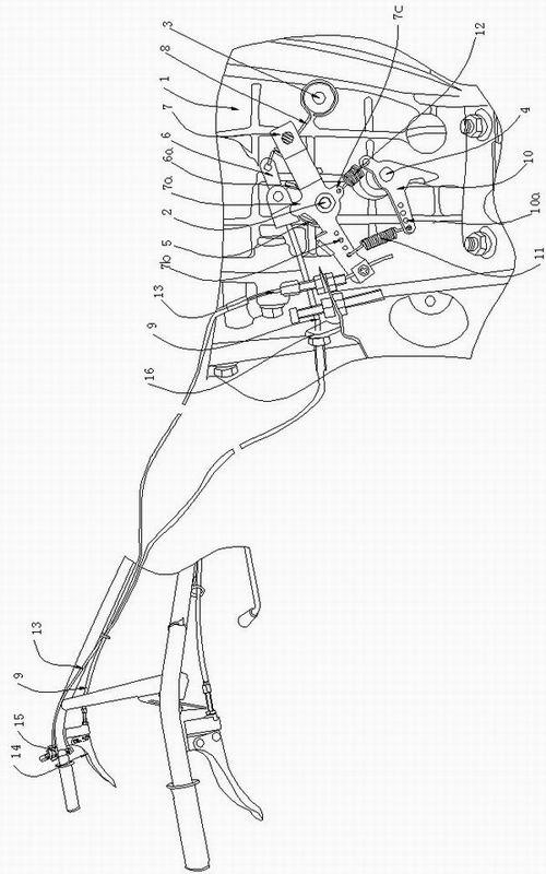
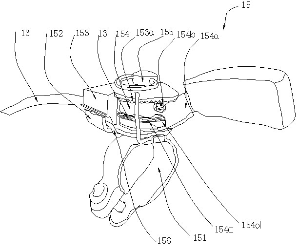
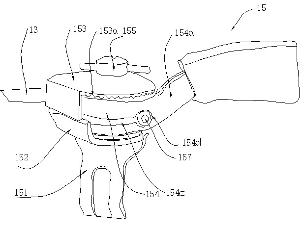
[0021] Such as Figure 1 ~ Figure 4The throttle control system of a tiller shown is provided with a control arm mounting column 2 and a spring mounting column 3 on the crankcase body 1, and the spring mounting column 3 is located on the right side of the control arm mounting column 2, and the Both the control arm mounting column 2 and the spring mounting column 3 are located above the throttle 4, and the throttle arm 10 is installed on the throttle 4, and the throttle return knob is sequentially set on the control arm mounting column 2 from the inside to the outside. Spring 5, reset support 6 and throttle control arm 7, wherein the inner end of the throttle return torsion spring 5 is fixed on the control arm mounting column 2, and the outer end is hooked on the left part of the throttle control arm 7; The lower end of the support 6 is installed on the mounti...


PUM


Abstract

The invention discloses an accelerator control system of a mini-tiller. A crank shaft box body is provided with an operating arm installation column and a spring installing column; an accelerator is provided with an accelerator arm; an accelerator return spring, a restoration support and an accelerator operating arm are sequentially sleeved on the operating arm installation column from inside to outside; the lower end of the restoration support is installed on the operating arm installation column; a return bracing wire spring is connected between the right end of the restoration support and the spring installation column; the left end of the restoration support is connected with an accelerator return bracing wire which is connected with a parking handle; the middle part of the accelerator operating arm is installed on the operating arm installation column; the middle part of the accelerator arm is installed on the accelerator; a refueling spring and an oil return spring which are respectively positioned at the left side and right side of the accelerator are connected between the accelerator operating arm and the accelerator arm; an accelerator wire is connected between the accelerator operating arm and the control device; and the restoration support and the accelerator operating arm are respectively and correspondingly provided with a pushing support lug and a stirring support lug. According to the invention, the accelerating, idling and parking of the mini-tiller can be realized well.

Description

technical field [0001] The invention relates to a tiller, in particular to an throttle control system for the tiller. Background technique [0002] In rural China, micro tillage machines are used more and more widely, and they play an increasingly important role in plowing, plowing, and farming. However, during the use of the tiller, many accidents have occurred, such as overturning when encountering obstacles, unskilled operators, operator tripping or other unexpected situations, so it is urgent to improve the controllability of the tiller . At present, most micro tillage machines realize walking and parking by installing a throttle control device on the micro tiller. This kind of throttle control device mainly includes a mounting seat, a positioning plate is arranged on the mounting seat, and a limit position is set above the positioning plate. The mounting seat, the positioning plate and the limiting plate are fixed through the same adjusting bolt, and an adjusting hand...

Claims


Application Information

Patent Timeline
Patent Type & Authority Applications(China)
IPC IPC(8): F02D11/02
Inventor 周树明张坤
Owner 周树明
Why Eureka
Try Eureka