
Optical fiber ring winding method

A manufacturing method and optical fiber technology, which are applied in the field of point-symmetrical winding of optical fiber rings, can solve the problems such as the inability to strictly guarantee the position of the center point of the optical fiber, and achieve the effects of easy installation and operation, lowering the full temperature temperature coefficient, and good anti-vibration performance.

Inactive Publication Date: 2011-07-06
中国航天科技集团公司第九研究院第十六研究所
View PDF0 Cites 28 Cited by
  • Summary
  • Abstract
  • Description
  • Claims
  • Application Information

AI Technical Summary

Problems solved by technology

[0007] The object of the present invention is to provide a fiber optic wrapping method, which solves the technical problem that the existing fiber optic wrapping method cannot strictly guarantee the position of the center point of the fiber

Method used


Image

  • Optical fiber ring winding method
  • Optical fiber ring winding method
  • Optical fiber ring winding method

Examples


Embodiment Construction

[0031] A method for wrapping an optical fiber, comprising the steps of:

[0032] 1] Calculate the required optical fiber length, measure the optical fiber of the calculated length, and leave enough optical fiber pigtails at both ends 5;

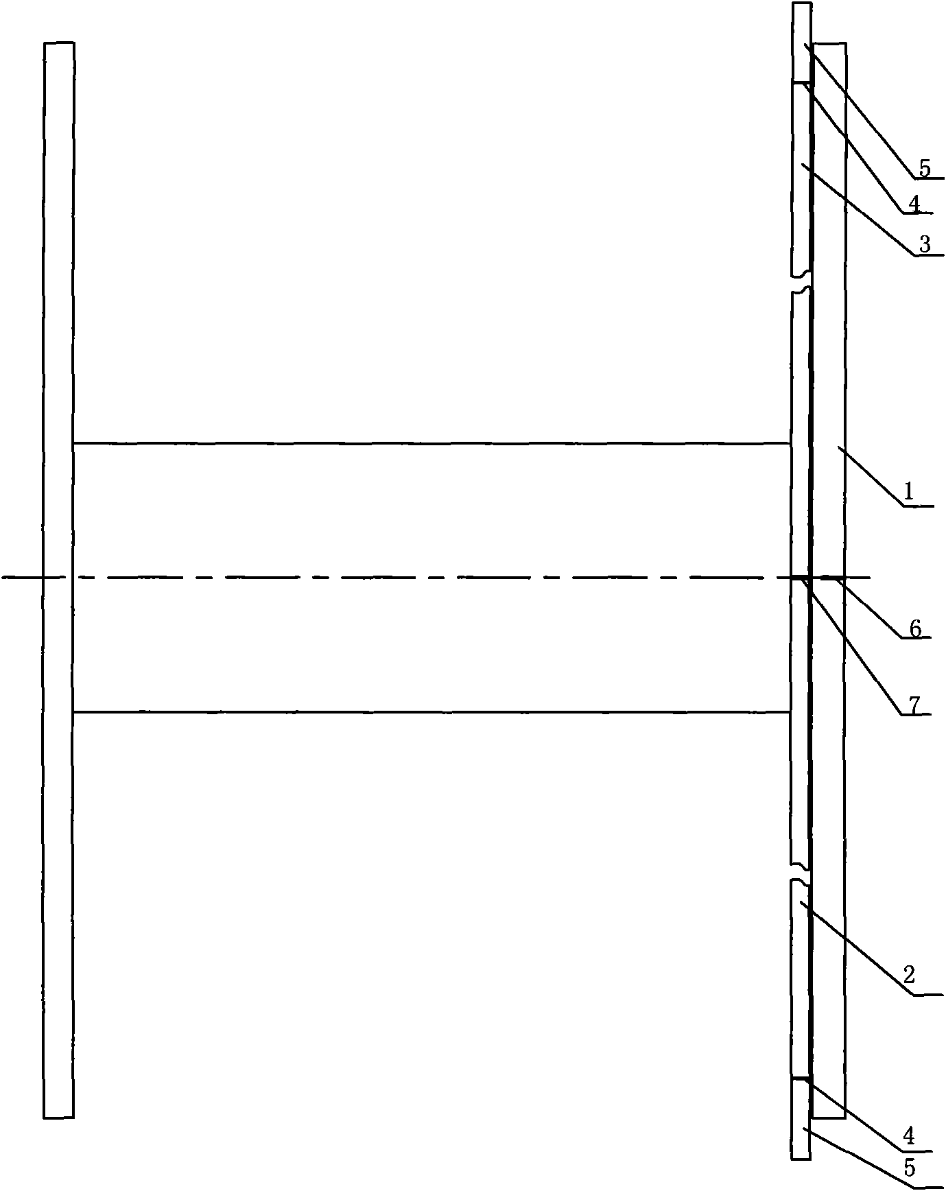
[0033] 2] Make an end point mark 4 at the two ends of the calculated length of the optical fiber, and make a midpoint mark 7 at the midpoint between the two end points of the optical fiber; make a straight line mark 6 on the outer circumference of the left wall of the skeleton 1 along the direction of the skeleton axis;

[0034] 3] Attach the optical fiber to the innermost part of the left wall of the fiber ring perpendicular to the axis of the frame 1, and align the fiber midpoint mark 7 with the straight line mark 6 of the frame;

[0035] 4] Wind the optical fiber according to the bipolar symmetrical winding method, quadrupole symmetrical winding method or octapole symmetrical winding method until the first half of the optical fiber 2 and t...


PUM


Abstract

The invention relates to an optical fiber ring winding method, comprising the following steps: the needed length of an optical fiber is computed and the optical fiber with the computed length is measured, and enough optical fiber pigtails are left at two ends of the optical fiber; end point marks at two end points of the optical fiber with the computed length are made, and the position of a middle point between two end points of the optical fiber is used as a midpoint mark; linear mark is made on the external circumferential surface of a left wall of a framework along the axis direction of the framework; the optical fiber is clung to the innermost part of the inner side of the left wall of an optical fiber ring in a manner that the optical fiber is vertical to the axis of the framework, and the midpoint mark of the optical fiber is aligned to the linear mark of the framework; the optical fiber is wound by adopting a bipolar symmetrical winding method, a dour-pole symmetrical winding method or an eight-pole symmetrical winding method until the optical fiber at the front half part and the optical fiber at the rear half part are wound at the respective end point mark positions; the two optical fiber pigtails are led out of the framework and are fixed. The method solves the technical problem that the existing optical fiber winding method can not strictly ensure the optical fiber to be aligned to the midpoint position, and reduces the whole temperature coefficient of an optical fiber gyro.

Description

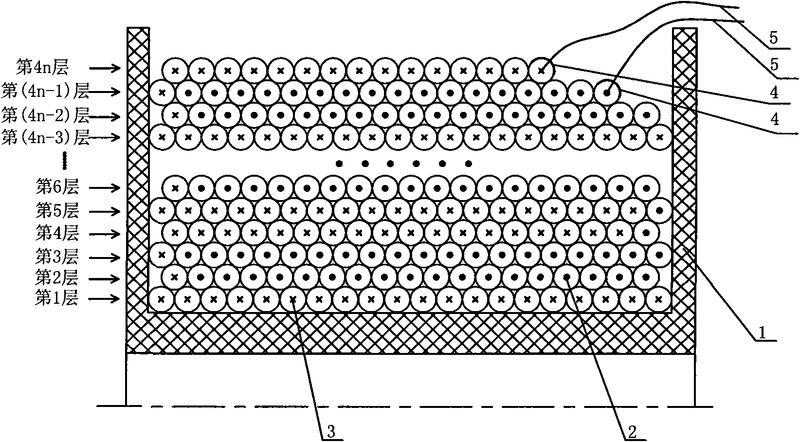
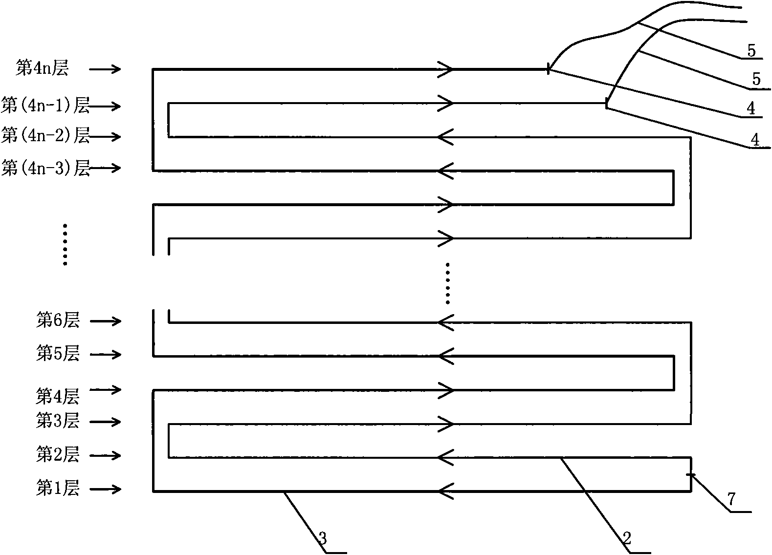
technical field [0001] The invention relates to an optical fiber winding method, in particular to a point-symmetrical winding method for an optical fiber ring. Background technique [0002] The quadrupole symmetrical winding method of the optical fiber ring can better reduce the influence of non-reciprocity, and it is relatively easy to realize. Most of the existing optical fiber rings belong to this winding method. The characteristic of this winding method is that the four-layer optical fiber coil is a cycle, and the symmetrical part of the midpoint of the optical fiber is in a close position in structure, such as figure 1 shown. The temperature-time gradient experienced by the symmetrical parts of the midpoint in the figure is quite close at the same time. If the thermal disturbances on the two sections of fiber symmetrical to the midpoint of the fiber are the same, the phase error caused by heat will be canceled out, which is exactly the choice The basis for the winding...

Claims


Application Information

Patent Timeline
IPC IPC(8): G01C19/72
Inventor 谢永周蓝燕吉世涛马小霞张力
Owner 中国航天科技集团公司第九研究院第十六研究所
Learn More