MR Sensor-based mobile phone state identification method and mobile phone

A technology of state identification and identification method, which is applied in the direction of telephone structure, electric/magnetic exploration, sound wave re-radiation, etc., can solve the problems of high identification cost and limited application occasions, and achieve high identification sensitivity and low manufacturing cost , Ease of use

Inactive Publication Date: 2011-07-06
SHANGHAI CHENXING ELECTRONICS SCI & TECH CO LTD
View PDF0 Cites 1 Cited by
  • Summary
  • Abstract
  • Description
  • Claims
  • Application Information

AI Technical Summary

Problems solved by technology

[0003] The technical problem to be solved by the present invention is to overcome the defects of high identification cost and limited application occasions in the state identification of existing electronic products such as mobile phones, and provide a method with high identification sensitivity, low cost, and unaffected application occasions. A limited method for mobile phone state recognition based on MR Sensor and a mobile phone using the MR Sensor for state recognition

Method used


Image

  • MR Sensor-based mobile phone state identification method and mobile phone
  • MR Sensor-based mobile phone state identification method and mobile phone
  • MR Sensor-based mobile phone state identification method and mobile phone

Examples


Embodiment 1

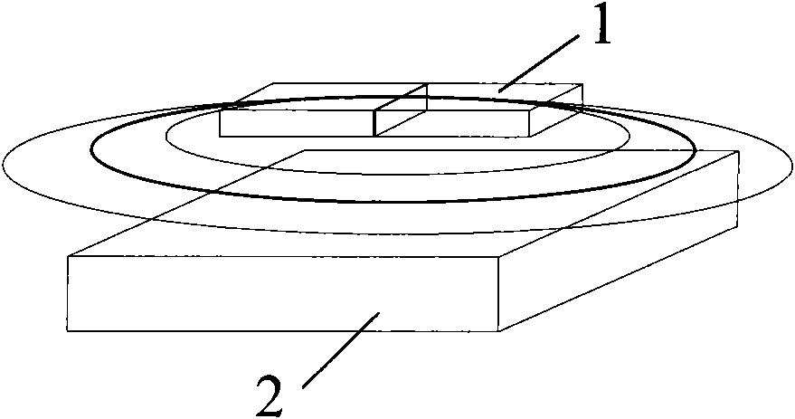
[0030] Such as figure 1 as shown, figure 1 It is the basic application schematic diagram of MR Sensor. The position of the magnet 1 can be above the MR Sensor 2, or on the same level as the MR Sensor 2, even if the magnet 1 and the MR Sensor 2 are slightly staggered, it can be identified.

Embodiment 2

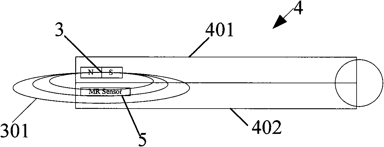
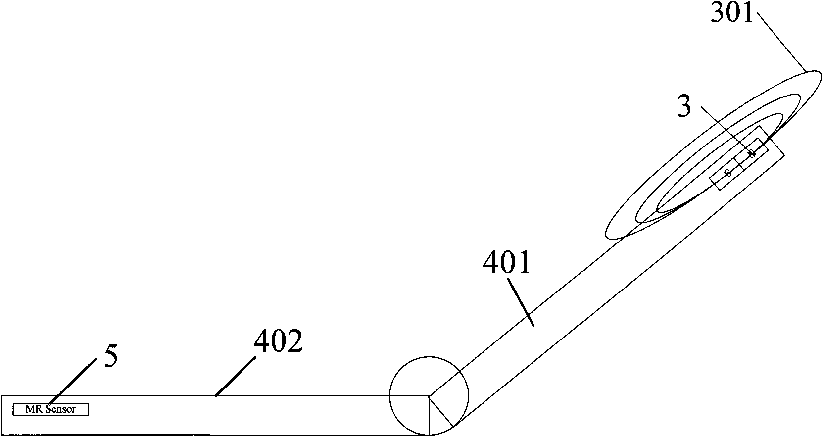
[0032] Such as figure 2 , image 3 Shown is a flip phone 4, figure 2 It is the structural diagram of MR Sensor applied to the clamshell mobile phone in the closed state, image 3 It is the structural diagram of MR Sensor applied to the flip phone in the open state. Place the polarity of the magnet 3 horizontally on the bottom edge of the top cover 401 of the flip phone 4, with the N pole or S pole of the magnet 3 facing the board tail, and the S pole or N pole being away from the board tail, passing through it horizontally by the magnetic force line 301 shown MR Sensor 5 is used to sense the opening and closing state of the flip phone 4 .

[0033] The state identification correspondence table is:

[0034] MR Sensor Status

[0035] The feature of this solution is that when the flip phone 4 is in the closed state, after opening it at a small angle, the signal fed back by the MRSensor 5 can identify that the flip phone 4 is in the open state.

Embodiment 3

[0037] The rotating screen mobile phone 6 has three states of forward closing and opening, and reverse closing. The state recognition and judgment scheme is as follows: Figure 4 , Figure 5 as shown, Figure 4 It is the application structure diagram of the MR Sensor solution on the rotating screen mobile phone in the forward closed state. Figure 5 It is the application structure diagram of the MR Sensor solution on the rotating screen mobile phone in the reverse closed state.

[0038] The magnet 8 is placed vertically on the screen 601 of the mobile phone. One pole of the magnetic pole is facing the tail of the board, and the other pole is away from the tail of the board.

[0039] The state identification correspondence table is:

[0040] The first MR Sensor

Second MR Sensor

phone status

With magnetic field

no magnetic field

Forward closing

no magnetic field

no magnetic field

open the cover

no magnetic field

With ...


PUM


Abstract

The invention discloses an MR Sensor-based mobile phone state identification method and a mobile phone. The method comprises the following steps of: 1, arranging at least one MR Sensor on the edge of an upper cover of the mobile phone; 2, arranging at least one magnet on the edge of a lower cover of the mobile phone in a way that a magnetic line of force of the magnet can horizontally run through the MR Sensor; 3, folding and unfolding the upper and lower covers of the mobile phone, and performing magnetic field induction detection on the MR Sensor; and 4, feeding a detection signal induced by the MR Sensor back to a central processing unit. The mobile phone capable of performing mobile phone state identification by using the MR Sensor comprises the central processing unit arranged in the mobile phone, and the magnet and the MR Sensor which are at least arranged on the upper and lower covers of the mobile phone respectively, wherein the magnetic line of force of the magnet horizontally runs through the MR Sensor when the upper and lower covers of the mobile phone are folded. The mobile phone is high in identification sensitivity, low in manufacturing cost and convenient to operate; and the method is used for identifying and judging the folding and unfolding state of various mobile phones.

Description

technical field [0001] The invention relates to a method for identifying the state of a mobile phone and the mobile phone, in particular to a method for identifying the state of opening and closing a mobile phone based on an MR Sensor and a mobile phone using the identification method. Background technique [0002] Nowadays, the appearance design requirements of electronic products are getting higher and higher, and the structure is more and more complex, such as mobile phones, the central processing unit of mobile phones needs to obtain the state of the mobile phone status, so as to correspond to different interfaces. There are two traditional mobile phone state recognition methods: one uses a proximity sensor: it relies on the emission of infrared rays to determine whether an object is approaching, thereby identifying the state of the mobile phone. Its disadvantages: complex structure, very high cost, and limited use occasions. The second is to use the Hall device: that i...

Claims


Application Information

Patent Timeline
Patent Type & Authority Applications(China)
IPC IPC(8): H04M1/02H04M1/725G01V3/00H04M1/72454
Inventor 黄颖
Owner SHANGHAI CHENXING ELECTRONICS SCI & TECH CO LTD
Why Eureka
Try Eureka