Device for quickly forming orthodontic ligature wire
A shaper and oral cavity technology, applied in the direction of arch wire, etc., can solve the problems of inconvenience, increase of treatment cost, increase of operating time of clinicians, etc., achieve humanized appearance and improve work efficiency
- Summary
- Abstract
- Description
- Claims
- Application Information
AI Technical Summary
Problems solved by technology
Method used
Image
Examples
Embodiment 1
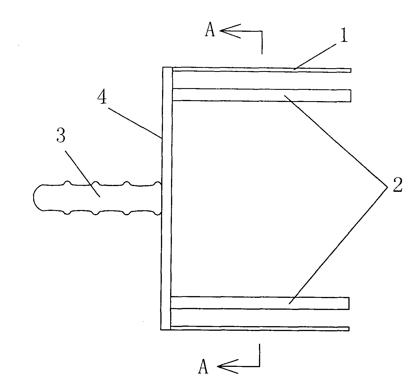
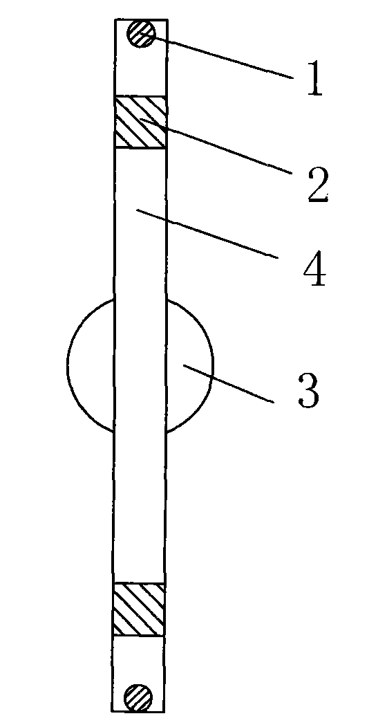
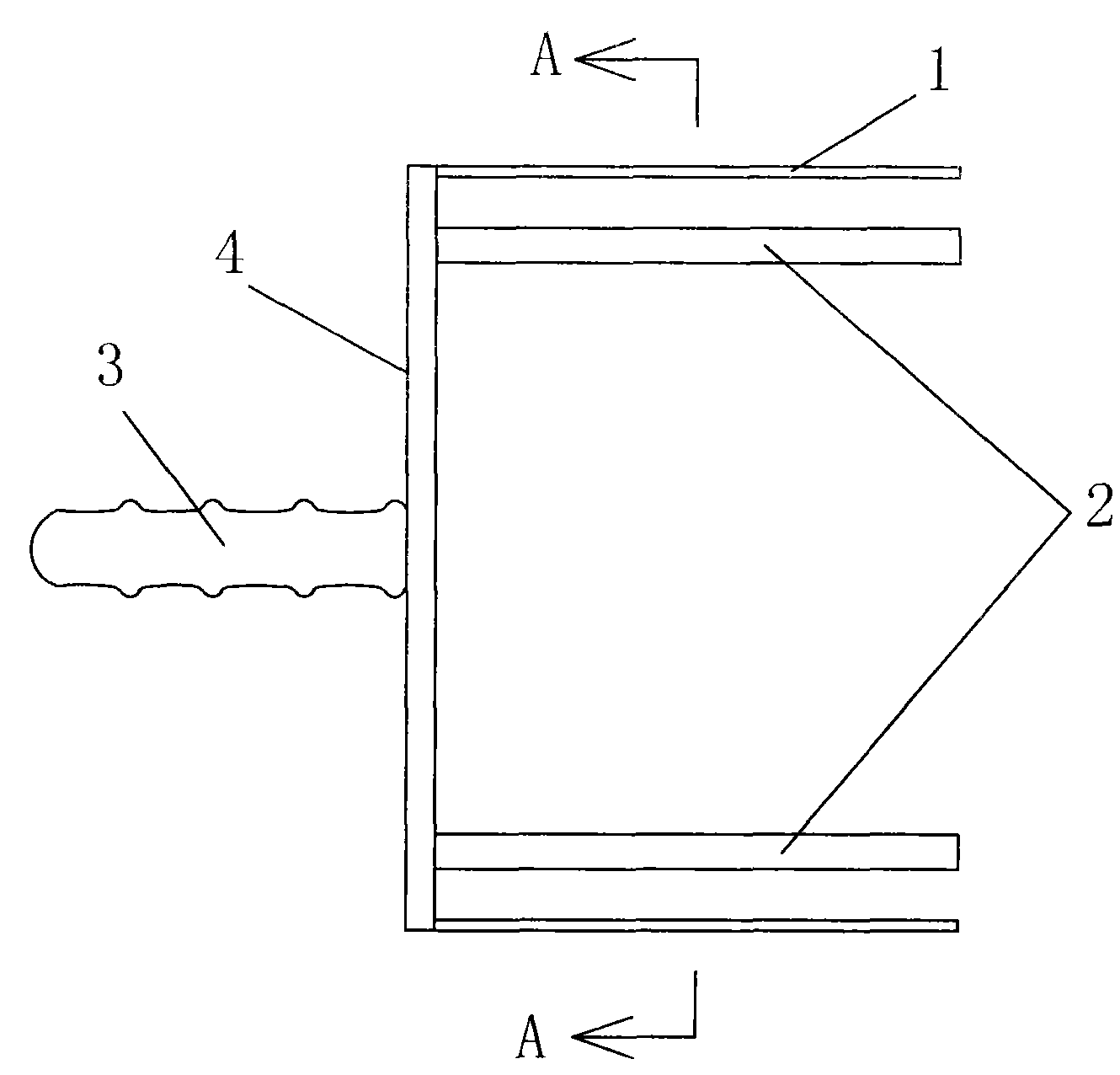
[0014] The two ends of the stainless steel side frame 1 are respectively connected with stainless steel round wires 4 in the orthodontic ligation wire rapid former, and two stainless steel square wires 2 with rounded rectangular cross-sections are respectively located inside the stainless steel round wires 4 and connected to the stainless steel side frame. 1 connection, two stainless steel round wires 4 and two stainless steel square wires 2 are parallel to each other, and the middle part of the other side of the stainless steel side frame 1 has a handle 3 that is in the same direction as the stainless steel round wire 4 and is vertically connected with the stainless steel side frame 1. The distance between the stainless steel round wire 4 and the stainless steel square wire 2 is 5 mm; the diameter of the stainless steel round wire 4 is 2 mm, and the cross section of the stainless steel square wire 2 is 5 mm × 6 mm, wherein the surface of 6 mm is opposite to the stainless steel ...
Embodiment 2
[0016] The two ends of the stainless steel side frame 1 are respectively connected with stainless steel round wires 4 in the orthodontic ligation wire rapid former, and two stainless steel square wires 2 with rounded rectangular cross-sections are respectively located inside the stainless steel round wires 4 and connected to the stainless steel side frame. 1 connection, two stainless steel round wires 4 and two stainless steel square wires 2 are parallel to each other, and the middle part of the other side of the stainless steel side frame 1 has a handle 3 that is in the same direction as the stainless steel round wire 4 and is vertically connected with the stainless steel side frame 1. The distance between the stainless steel round wire 4 and the stainless steel square wire 2 is 3 mm; the diameter of the stainless steel round wire 4 is 2 mm, and the cross section of the stainless steel square wire 2 is 5 mm × 6 mm, wherein the surface of 6 mm is opposite to the stainless steel ...
Embodiment 3
[0018] The two ends of the stainless steel side frame 1 are respectively connected with stainless steel round wires 4 in the orthodontic ligation wire rapid former, and two stainless steel square wires 2 with rounded rectangular cross-sections are respectively located inside the stainless steel round wires 4 and connected to the stainless steel side frame. 1 connection, two stainless steel round wires 4 and two stainless steel square wires 2 are parallel to each other, and the middle part of the other side of the stainless steel side frame 1 has a handle 3 that is in the same direction as the stainless steel round wire 4 and is vertically connected with the stainless steel side frame 1. The handle 3 is provided with a wave groove for easy grasping and the direction of the handle 3 is perpendicular to the stainless steel side frame 1, and the two outer stainless steel wires are stainless steel round wires 4 with a diameter of 2 mm, and the distance between them is 8 cm; The squa...
PUM
 Abstract
Description
Claims
Application Information
 - R&D
- Intellectual Property
- Life Sciences
- Materials
- Tech Scout
- Unparalleled Data Quality
- Higher Quality Content
- 60% Fewer Hallucinations
Browse by: Latest US Patents, China's latest patents, Technical Efficacy Thesaurus, Application Domain, Technology Topic, Popular Technical Reports.
© 2025 PatSnap. All rights reserved.Legal|Privacy policy|Modern Slavery Act Transparency Statement|Sitemap|About US| Contact US: help@patsnap.com


