Anti-drop cable hook for transfer conveyor

A loader and cable technology, which is applied to conveyors, earthwork drilling, transportation and packaging, etc., can solve the problems of cables falling off and affecting the normal operation of the loader, and achieve the effect of preventing cables from falling off and ensuring normal work.

Active Publication Date: 2011-07-13
YANKUANG GROUP CONTINENT MACHINERY +1
View PDF7 Cites 0 Cited by
  • Summary
  • Abstract
  • Description
  • Claims
  • Application Information

AI Technical Summary

Problems solved by technology

[0004] The reloading machine needs necessary cables when it is in use. At present, the cables are usually placed on the bridge section of the reloading machine, but because the reloading machine moves during work, the cable will fall off from the winding coil, which will affect the normal operation of the reloading machine

Method used


Image

  • Anti-drop cable hook for transfer conveyor
  • Anti-drop cable hook for transfer conveyor
  • Anti-drop cable hook for transfer conveyor

Examples


Embodiment 1

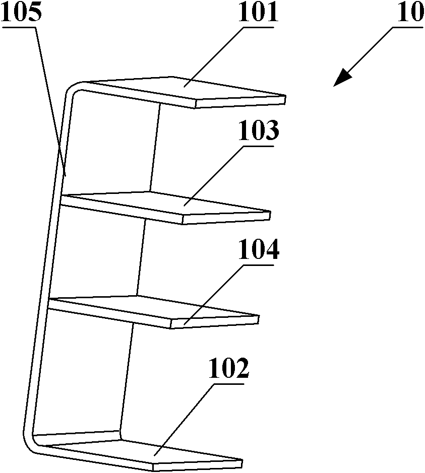
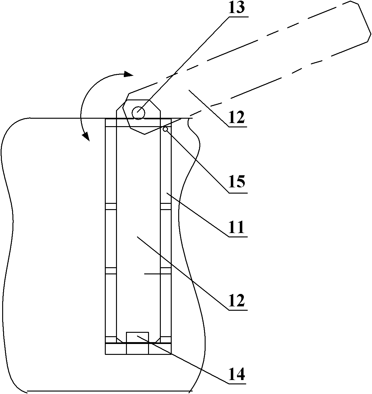
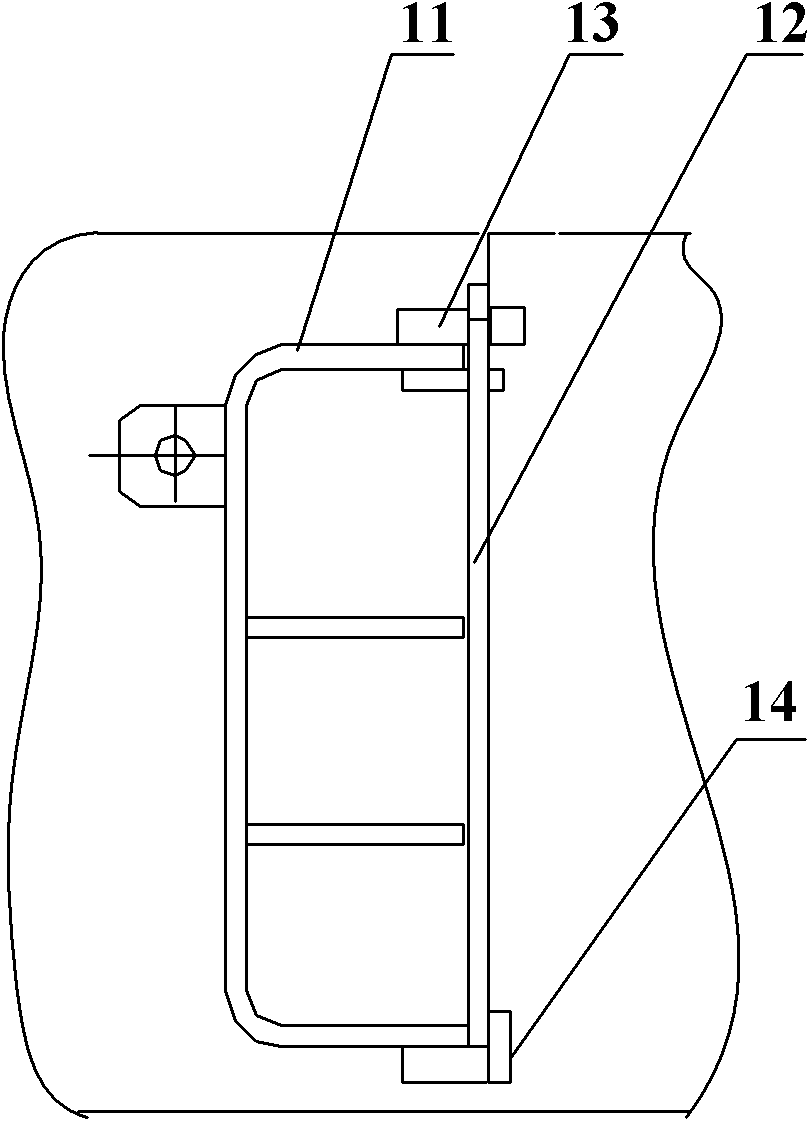
[0049] Please refer to figure 2 with image 3 As shown, the present invention provides a detachment-proof cable hook for the reloading machine 1, so as to prevent the cables wound on the reloading machine from falling off, so as to ensure the normal operation of the reloading machine. It includes: a cable hook frame 11, a shaft 13, a baffle plate 12 and a locking part 14, wherein the baffle plate 12 is hinged on the top plate of the cable hook frame 11 through the shaft 13, and can rotate on the plane where the baffle plate 12 is located; the baffle plate 12 A locking component 14 that resists the rotation of the baffle plate 12 is provided on it.

[0050] The above-mentioned shaft 13 is a swivel component that ensures that the baffle 12 rotates on its own plane, wherein one end of the shaft 13 is fixed to the cable hook frame 11, and the other end is hinged to the baffle 12, that is, the baffle 12 is provided with a through hole. The shaft 13 passes through the through hol...

Embodiment 2

[0056] For the anti-off cable hook on the reloading machine in the embodiment of the present invention, please refer to Figure 7 with 8 , comprising: a cable hook frame 21, two slide rails 23, a baffle plate 22 and a handle 22, wherein the two slide rails 23 are relatively arranged on the cable hook frame 21, and the two slide rails 23 and Figure 7 The direction shown by the middle arrow is parallel, and the slide rail 23 can be fixed on the cable hook frame 21 by bolts, or can be fixed on the cable hook frame 21 by welding; a handle 25 can also be set on the baffle plate 22, and the baffle plate can be moved 22 Move in the direction indicated by the arrow.

[0057] The above-mentioned detachment-proof cable hook used on the reloading machine can also be provided with a locking part 24 that resists the movement of the baffle plate 22 when it is placed at a predetermined position. The function of the locking part 24 prevents the baffle 22 from continuing to move when it mov...

Embodiment 3

[0060] For the anti-off cable hook of reloading machine 1 in the embodiment of the present invention, please refer to Figure 12 , including: a cable hook frame 31 and one end is fixed on the bottom plate of the cable hook frame 31, and the other end is detachably installed on the top plate of the cable hook frame 31 through a locking component 33. The locking part 33 is a pin shaft, and the pin shaft protrudes from the upper surface of the top plate of the cable hook frame.


PUM


Abstract

The embodiment of the invention discloses an anti-drop cable hook for a transfer conveyor. The anti-drop cable hook comprises a cable hook frame, a shaft, a baffle and a locking component, wherein the baffle is hinged on a top plate of the cable hook frame through the shaft, and can rotate on a plane at which the baffle is located; and the locking component resisting the baffle rotation is arranged on the baffle. When the cable is arranged on the transfer conveyor, a cable in the cable hook frame is blocked by rotating the baffle and tensioned by the locking component. The anti-drop cable hook can effectively prevent the cable from dropping and ensure the normal work of the transfer conveyor.

Description

technical field [0001] The invention relates to the field of mining equipment, in particular to a detachment-preventing cable hook used on a loader. Background technique [0002] The full name of the reloading machine is the scraper reloading machine for trough, which is a bridge-type scraper conveyor installed in the section transportation roadway at the exit of the mine working face. It is mainly used for high-yield, high-efficiency and comprehensive mechanized working face reloading and transporting coal along the trough. It can be used in conjunction with scraper conveyors, crushers and belt conveyors on the working face. It can move along it as a whole, so that the transfer machine can be adjusted as a whole with the progress of the working face conveyor, and the coal is transferred from the working face conveyor to the retractable belt conveyor through the bridge transfer machine. [0003] When working, one end is overlapped with the conveyor on the working face, and ...

Claims


Application Information

Patent Timeline
IPC IPC(8): B65G19/18E21F13/00
Inventor 刘伟亮陈勤伟刘金成于孔玉
Owner YANKUANG GROUP CONTINENT MACHINERY
Why Eureka
Try Eureka