Double-chamber hydragass spring

A technology of oil-pneumatic springs and double air chambers, applied in springs, spring/shock absorbers, gas-hydraulic shock absorbers, etc., can solve problems such as troublesome maintenance, inconvenient installation and layout, and gas leakage, and achieve convenient maintenance and structural Simple, good sealing effect

Active Publication Date: 2011-07-13
中国航天三江集团公司特种车辆技术中心
View PDF5 Cites 5 Cited by
  • Summary
  • Abstract
  • Description
  • Claims
  • Application Information

AI Technical Summary

Problems solved by technology

However, the existing dual-chamber oil-pneumatic springs are rarely used in vehicles due to the separation of the main chamber and the counter-pressure chamber, which have the disadvantages of large volume, high weight, and inconvenient installation and arrangement
Moreover, the existing single-chamber oil-gas springs and double-chamber oil-gas springs have the disadvantage of poor sealing. During use, the internal gas will leak slowly, requiring special inflation equipment and inflating in time according to the operating procedures, and maintenance is troublesome.

Method used


Image

  • Double-chamber hydragass spring
  • Double-chamber hydragass spring
  • Double-chamber hydragass spring

Examples


Embodiment Construction

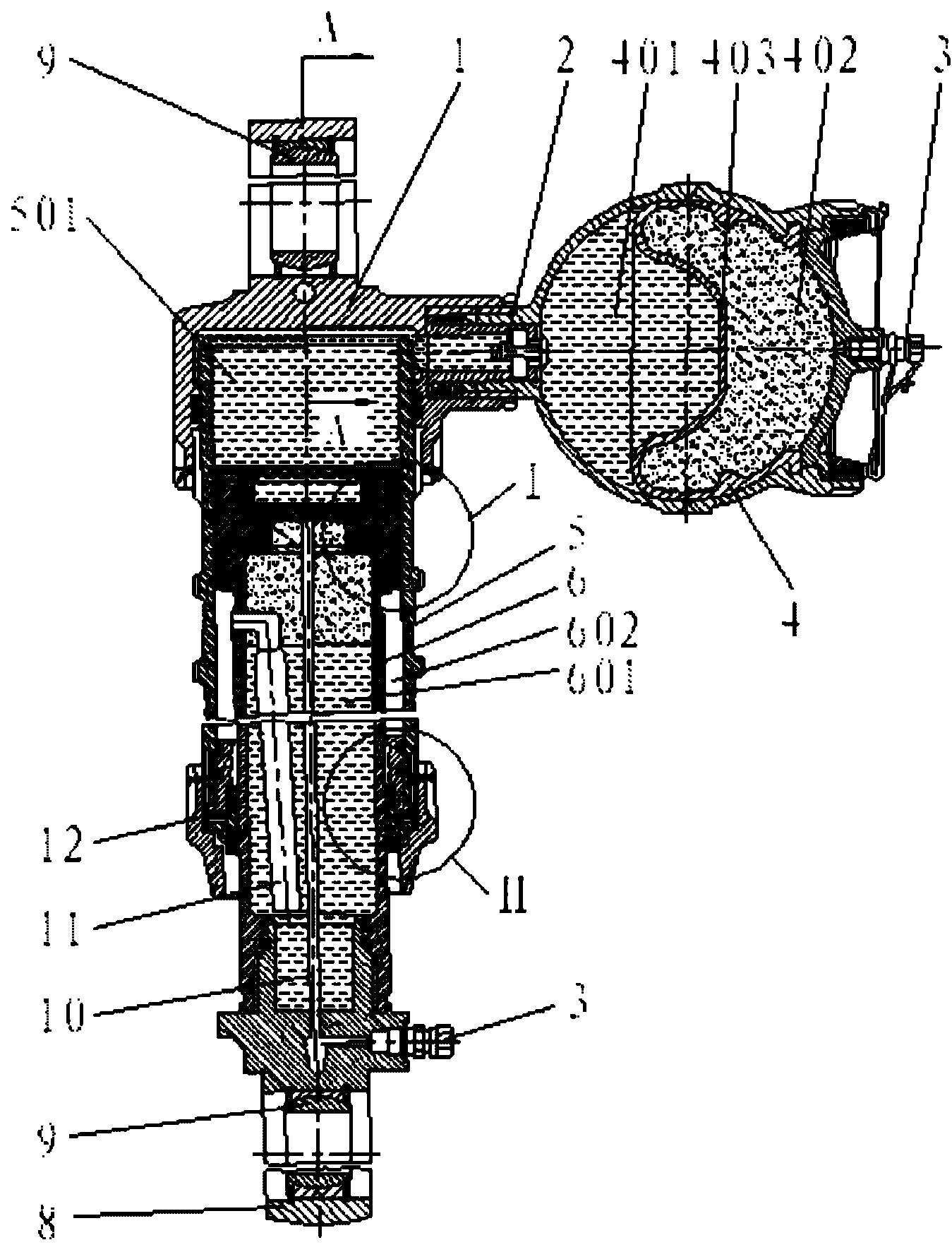
[0018] Such as figure 1 As shown, a double-chamber oil-pneumatic spring mainly includes an upper lug 1, a lower lug 8, a master cylinder 5, an elastic component 4, a back pressure cylinder 6, a piston and a guide pipe 10 and the like. The upper lug 1 is located at the top of the master cylinder 5, and the lower lug 8 is located at the bottom of the back pressure cylinder 6, and they are connected by a threaded structure. Bearings 9 are installed inside the upper lug 1 and the lower lug 8, the side of the upper lug 1 is connected with the elastic part 4, the piston and the guide tube 10 are installed in the back pressure cylinder 6, and the back pressure cylinder 6 is integrated with the piston and the guide tube 10 And installed in the cylinder body of the master cylinder 5, the space between the upper surface of the piston and the master cylinder 5 and the space below the upper lug 1 together forms the main chamber 501, the main chamber 501 and the elastic member oil chamber ...


PUM


Abstract

The invention relates to a double-chamber hydragass spring which comprises an upper lug, a lower lug, a main cylinder, an elastic component, a back pressure cylinder, a piston, a guide pipe and the like, wherein the upper lug is positioned at the upper part of the main cylinder; the lower lug is positioned at the lower part of the back pressure cylinder, the upper lug and the main cylinder are connected through a thread structure, and the lower lug and the back pressure cylinder are connected through a thread structure; the upper lug and the lower lug are both provided with a bearing internally; the side part of the upper lug is connected with the elastic component; and the piston and the guide pipe are installed in the back pressure cylinder. The double-chamber hydragass spring is characterized in that the back pressure cylinder, the piston and the guide pipe are connected into a whole and installed in the cylinder body of the main cylinder; a main cavity is formed by a space among the upper surface of the piston, the main cylinder and the space below the upper lug; a main air chamber is formed by the main cavity, an elastic component oil liquid chamber of the elastic component and an air chamber; a back pressure air chamber is formed by a back pressure chamber in the back pressure cylinder and a ring chamber positioned between the main cylinder and the back pressure cylinder; the back pressure chamber and the ring chamber are connected through a connecting pipe. The double-chamber hydragass spring has the beneficial effects of simple structure, small size, light weight, good tightness and large bearing tonnage and is convenient to arrange and install.

Description

technical field [0001] The invention relates to a double-air chamber oil-gas spring, which belongs to the technical field of motor vehicle suspension and is used as an elastic component and a hydraulic shock absorber of the vehicle suspension. Background technique [0002] There are two types of oil-pneumatic springs currently used on vehicles: one is a single-chamber oil-pneumatic spring, and the other is a double-chamber oil-pneumatic spring. At present, single-chamber oil-pneumatic springs are most used in vehicles. This type of oil-pneumatic spring has the advantages of small size, low weight, and easy installation and layout. It is mainly used in heavy vehicles. However, this oil-pneumatic spring has a big disadvantage, that is, the spring will stretch very long when the vehicle is low-loaded or unloaded, and the lower the stiffness, the greater the elongation, which will cause the vehicle to produce serious roll when turning , Even when the vehicle is running, acciden...

Claims


Application Information

Patent Timeline
Patent Type & Authority Applications(China)
IPC IPC(8): F16F9/06F16F9/54F16F9/34
Inventor 王新郧毛楚男谷明起徐照丽张波
Owner 中国航天三江集团公司特种车辆技术中心
Why Eureka
Try Eureka