Method and device for measurement of nanometer resolution total reflection differential micrometric displacement
What is AI technical title?
AI technical title is built by PatSnap AI team. It summarizes the technical point description of the patent document.
A total reflection and differential technology, applied in the direction of measuring devices, optical devices, instruments, etc., can solve the problems of limited resolution, influence, expensive system, etc., and achieve the effect of improving sensitivity
Inactive Publication Date: 2012-07-04
ZHEJIANG UNIV
View PDF1 Cites 0 Cited by
Summary
Abstract
Description
Claims
Application Information
AI Technical Summary
This helps you quickly interpret patents by identifying the three key elements:
Problems solved by technology
Method used
Benefits of technology
Problems solved by technology
However, its resolution is limited by the size of the pinhole and the numerical aperture of the microscope objective, and is affected by the fluctuation of the external background and the light source itself.
In order to improve its axial resolution, Zhao Weiqian and others proposed the idea of differential confocal in the Chinese invention patent No. The light intensity after passing through the two small holes is then differentially processed, which improves the axial resolution and eliminates the influence of optical power fluctuations and background noise on the measurement, but it requires two small holes, two detectors and adjustment Relatively complex and thus expensive system
Method used
Image
Click on the blue label to locate the original text in one second.
Reading with bidirectional positioning of images and text.
Examples
Embodiment 1
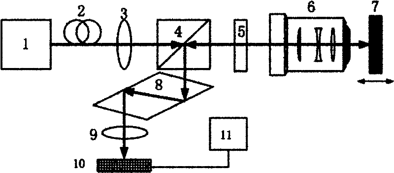
[0042] Such as figure 1 As shown, a device for measuring nanometer-resolution total reflection differential micro-displacement, including: laser 1, single-mode fiber 2, collimator lens 3, polarization beam splitter 4, λ / 4 wave plate 5, microscope objective lens 6, the measured A target mirror 7 , a rhombic prism 8 , a convex lens 9 , a differential detector 10 , and a drive and display unit 11 .
[0043] The laser 1, the single-mode optical fiber 2 and the collimating lens 3 constitute the first component group in sequence, the polarization beam splitter 4 is the second component group, and the first component group and the second component group are sequentially located on the optical path of the light emitted by the laser 1; The λ / 4 wave plate 5 and the microscopic objective lens 6 constitute the third component group, which are sequentially located on the first transmission light path of the polarization beam splitter 4 with the target lens 7 to be measured; the rhomboid pr...
Embodiment 2
[0058] Such as Figure 7 As shown, a device for measuring nanometer-resolution total reflection differential micro-displacement, including: laser 1, single-mode fiber 2, collimator lens 3, polarization beam splitter 4, λ / 4 wave plate 5, microscope objective lens 6, the measured A target mirror 7 , a rhombic prism 8 , a convex lens 9 , a differential detector 10 , and a drive and display unit 11 .
[0059] The laser 1, the single-mode optical fiber 2 and the collimating lens 3 constitute the first component group in sequence, the polarization beam splitter 4 is the second component group, and the first component group and the second component group are sequentially located on the optical path of the light emitted by the laser 1; The λ / 4 wave plate 5 and the microscopic objective lens 6 constitute the third component group, which are sequentially located on the first reflected light path of the polarizing beam splitter 4 with the measured target mirror 7; the rhomboid prism 8, c...
PUM
Abstract
The invention discloses a method and device for measurement of nanometer resolution total reflection differential micrometric displacement. The device comprises a laser device, a single-mode fiber, a collimating lens, a polarizing beam splitter, a lambda / 4 wave plate, a micro objective, a detected target lens, a rhombic prism, a convex lens, a differential detector and a driving and display unit.The method comprises steps as follows: after being filtered, collimated and split by polarization, laser sequentially passes through a fast axis and the lambda / 4 wave plate and micro objective to reach the detected target lens, wherein the included angle between the lambda / 4 wave plate and micro objective and the polarization direction of vertical incidence light beam is 45 degrees; after being reversed, the laser passes through the micro objective and lambda / 4 wave plate, and then vertically enters the polarizing beam splitter again; then, the laser enters the rhombic prism, is subjected to total reflection in the rhombic prism, and exits; and finally, after being collected, the laser enters the differential detector for processing, thus obtaining a signal for reflecting the position change of the detected target lens, and displaying the position change of the detected target lens. The invention can be used for detecting the manometer resolution and can be widely applied to the industrial precision measurement and monitoring fields.
Description
technical field [0001] The invention belongs to the technical field of photoelectric detection, and in particular relates to a method and a device for high-precision micro-displacement measurement and monitoring. Background technique [0002] Today, nanotechnology, biotechnology, and high-end integrated circuit manufacturing technology have become important directions for the development of world science and technology. Fast and reliable nanoscale resolution detection technology plays an extremely important role in the research of nanotechnology, biotechnology, high-end integrated circuit manufacturing and other fields. The traditional microscopic measurement technology based on light interference has been able to obtain measurement resolutions as high as below 1nm. At present, the optical non-interference method for micro-displacement measurement is the most successful confocal method. The traditional confocal method is to use the point light source, the object to be measu...
Claims
Application Information
Patent Timeline
Application Date:The date an application was filed.
Publication Date:The date a patent or application was officially published.
First Publication Date:The earliest publication date of a patent with the same application number.
Issue Date:Publication date of the patent grant document.
PCT Entry Date:The Entry date of PCT National Phase.
Estimated Expiry Date:The statutory expiry date of a patent right according to the Patent Law, and it is the longest term of protection that the patent right can achieve without the termination of the patent right due to other reasons(Term extension factor has been taken into account ).
Invalid Date:Actual expiry date is based on effective date or publication date of legal transaction data of invalid patent.

