
Method and device for mapping demodulation reference signals (DMRS)

A technology for demodulating reference symbols and mapping methods, which is applied in the field of mapping methods and devices for demodulating reference symbols, can solve problems such as mutual cancellation, and achieve the effect of improving accuracy

Active Publication Date: 2011-07-13
ZTE CORP
View PDF2 Cites 23 Cited by
  • Summary
  • Abstract
  • Description
  • Claims
  • Application Information

AI Technical Summary

Problems solved by technology

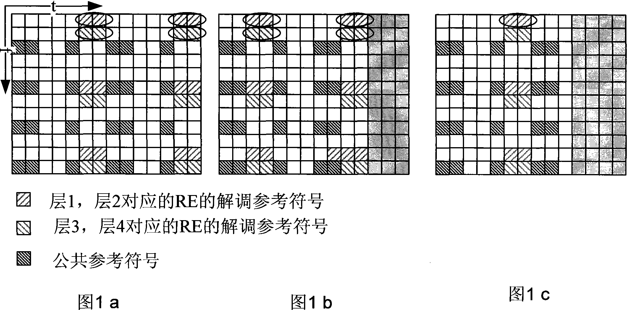
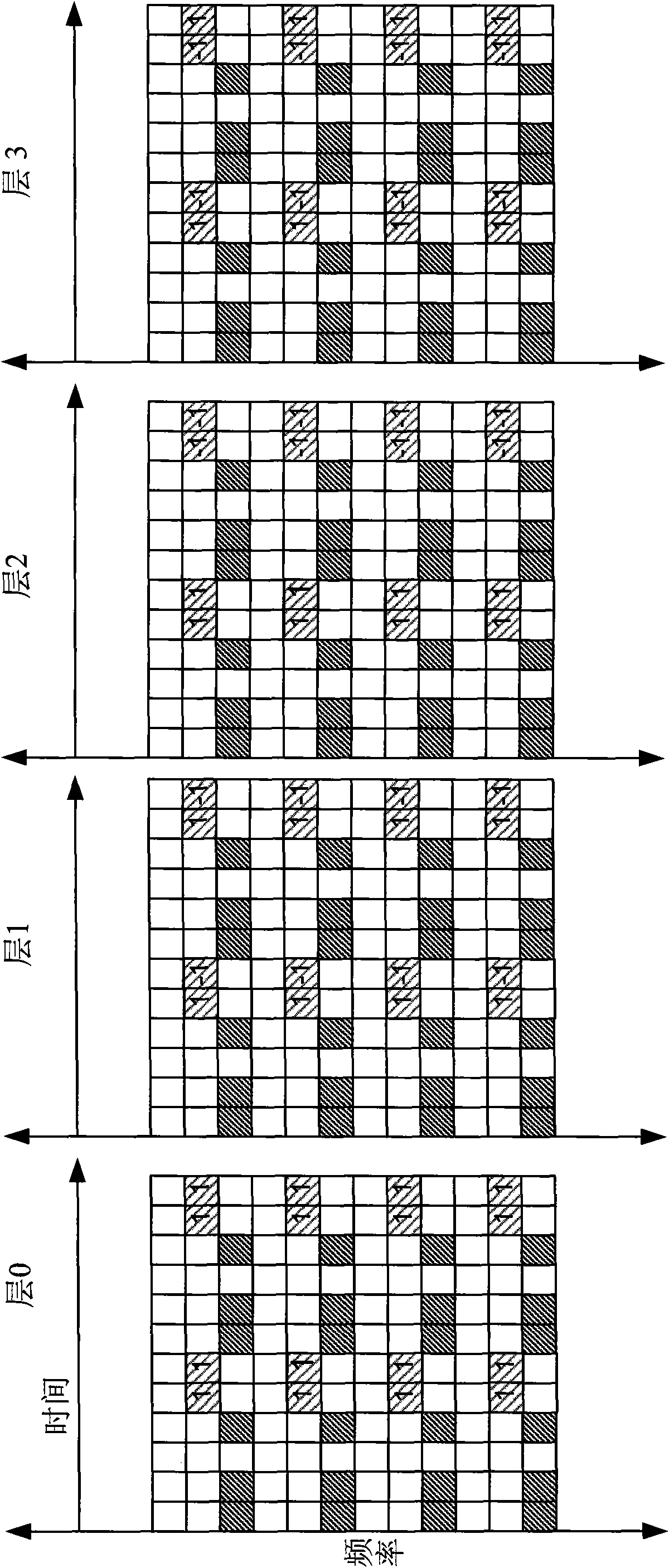
When multiple layers are code-division multiplexed and the layers are orthogonal, the corresponding sequences of the multiple layers are the same before being processed with a mask. Therefore, when the pilots processed with OCC are precoded, On some antenna ports, the pilot signals will superimpose and enhance each other, while on some antenna ports they will cancel each other out.

Method used


Image

  • Method and device for mapping demodulation reference signals (DMRS)
  • Method and device for mapping demodulation reference signals (DMRS)
  • Method and device for mapping demodulation reference signals (DMRS)

Examples


Embodiment Construction

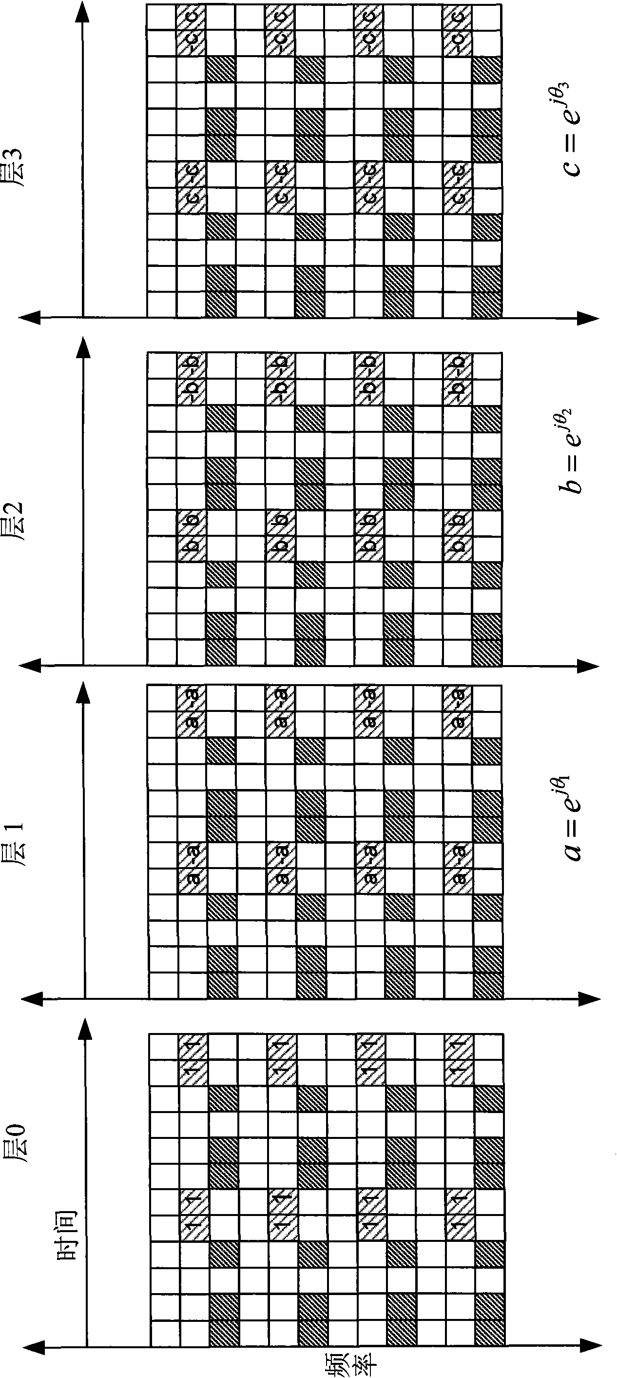
[0046] In the present invention, the DMRS sequence is multiplied by different phase factors to generate the DMRS sequence corresponding to each layer, which can avoid mutual cancellation of DMRS during precoding after OCC mapping.

[0047] Specifically, the method of the embodiment of the present invention includes: generating a demodulation reference symbol (DMRS) sequence, multiplying the DMRS sequence by different phase factors, generating a DMRS sequence corresponding to each layer, and performing an orthogonal mask (OCC) process , mapped to a physical resource block (PRB, Physical ResourceBlock).

[0048] The generated DMRS sequence is based on the same n SCID The sequence generated by the parameters; the layers corresponding to the multiplication by different phase factors are the layers for code division multiplexing, and the above processing is performed on the scheduled resources.

[0049] Wherein, preferably, the phase value of the phase factor is different from the...


PUM


Abstract

The invention discloses a method and device for mapping demodulation reference signals (DMRS). The method comprises the following steps: generating DMRS sequences, multiplying the DMRS sequences by different phase factors respectively to generate DMRS sequences corresponding to each layer, carrying out orthogonal code cover (OCC) treatment on the DMRS and mapping the DMRS on physical resource blocks (PRB). The method and the device have the following beneficial effects: the problems of mutual offset and mutual reinforcement of the DMRS are avoided in the precoding process by multiplying the same DMRS by different phase factors respectively and mapping the DMRS on different layers, thus improving the precision of channel estimation.

Description

technical field [0001] The present invention relates to the communication field, in particular to a mapping method and device for demodulation reference symbols. Background technique [0002] The high-order multi-antenna technology is one of the key technologies of the Long Term Evolution Advanced (LTE-A or LTE-Advanced, Long Term Evolution Advanced) system, and is used to increase the system transmission rate. In order to achieve channel quality measurement and data demodulation after the introduction of high-order multi-antenna technology, the LTE-Advanced system defines two types of pilot symbols: demodulation reference symbols (DMRS, Demodulation ReferenceSignal) and channel quality measurement reference symbols (CSI- RS, Channel State Information-Reference Signal), wherein the DMRS is used for demodulation of a Physical Downlink Shared Channel (PDSCH, PhysicalDownlink Shared Channel). CSI-RS for CSI (channel state information) measurement is used for channel quality in...

Claims


Application Information

Patent Timeline
Patent Type & Authority Applications(China)
IPC IPC(8): H04L1/06H04L25/03
Inventor 孙云锋姜静张文峰张峻峰
Owner ZTE CORP
Learn More