
Method for eccentrically orienting a laser cutting beam in relation to a nozzle axis and for cutting at an angle, corresponding laser machining head and laser machining tool

A laser processing machine and laser cutting technology, applied in laser welding equipment, metal processing equipment, manufacturing tools, etc., to achieve the effect of improving melt discharge

Active Publication Date: 2011-07-13
TRUMPF WERKZEUGMASCHINEN GMBH & CO KG
View PDF8 Cites 23 Cited by
  • Summary
  • Abstract
  • Description
  • Claims
  • Application Information

AI Technical Summary

Problems solved by technology

[0003] However, the above-mentioned laser beam bevel cutting process has so far been absolutely not advantageous, that is to say the laser beam bevel cutting has to be significantly reduced in feed compared to laser cutting with a laser cutting beam oriented perpendicularly to the workpiece surface ( up to 70% at a 45° bevel cut angle) and at the expense of significant mass loss

Method used


Image

  • Method for eccentrically orienting a laser cutting beam in relation to a nozzle axis and for cutting at an angle, corresponding laser machining head and laser machining tool
  • Method for eccentrically orienting a laser cutting beam in relation to a nozzle axis and for cutting at an angle, corresponding laser machining head and laser machining tool
  • Method for eccentrically orienting a laser cutting beam in relation to a nozzle axis and for cutting at an angle, corresponding laser machining head and laser machining tool

Examples


Embodiment Construction

[0033] Figure 1a Shown is a tubular workpiece 1 on which a 45° incision is made with a flat cutting surface 1b that can be formed at 90° with an additional (not shown) tubular workpiece with a flat cutting surface Corner cases are welded along the thin weld seam connecting these cut faces. In order to produce a flat cutting surface 1b, it is necessary to perform a bevel cutting process on the tubular workpiece 1, in which the bevel cutting angle α (see Figure 1b ) varies in the range between −45° and 45°, because a distorted cut surface is produced on the workpiece 1 during conventional cutting with a constant bevel angle α.

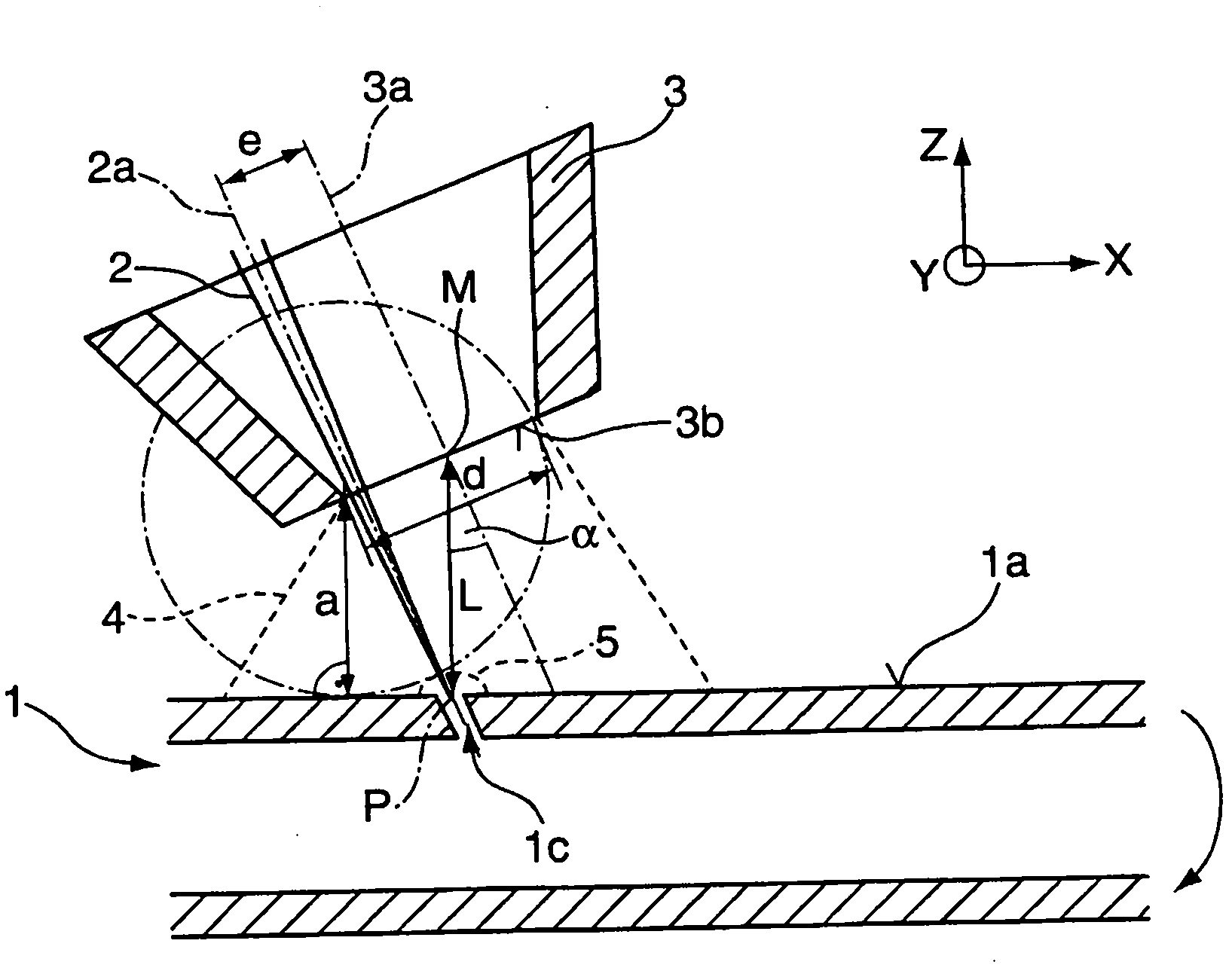
[0034] Figure 1b A transient diagram showing such a laser beam bevel cutting process on a tubular workpiece 1 at a bevel cutting angle α of approximately 20°, at which the laser cutting beam 2 with its beam axis 2a is relative to the workpiece surface 1a Orientation of the face normal on . The nozzle axis 3 a of the cutting gas nozzle 3 is oriented...


PUM


Abstract

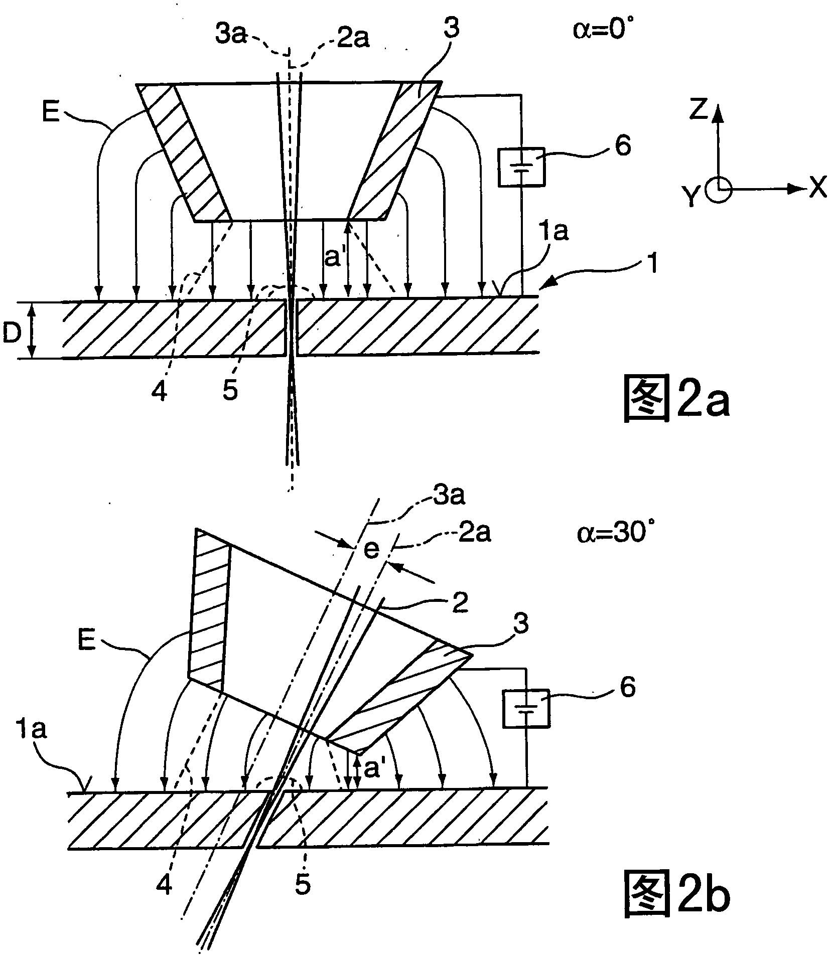
The invention relates to a method for the laser beam cutting at an angle of a workpiece (1). According to said method, a supersonic cutting gas stream (4) emerging from a cutting gas nozzle (3) is oriented at an oblique cutting angle (alpha) in relation to the workpiece surface (1a), the workpiece (1) and the laser cutting beam (2) being displaced in relation to each other during laser beam cutting at an angle. The oblique cutting angle (alpha) extends perpendicular to the direction of advance (Y). During the relative movement, the position (P) of the laser cutting beam (2) on the surface of the workpiece (1a) is adjusted such that the laser cutting beam (2) is incident on the surface of the workpiece (1a) in a high pressure area (5) formed within the supersonic cutting gas stream (4). The invention also relates to a laser machining tool for carrying out said method.

Description

technical field [0001] The invention relates to a method for oblique laser beam cutting of workpieces, in which method the ultrasonic cutting gas flow discharged from the cutting gas nozzle is oriented at an oblique cutting angle with respect to the surface of the workpiece, in which the workpiece and the laser The cutting beams are moved relative to each other, wherein the bevel cutting angle runs at right angles to the feed direction. The invention also relates to a laser processing machine for oblique cutting of a workpiece by a laser beam, comprising: a cutting gas nozzle for generating an ultrasonic cutting gas flow, which can be oriented at an oblique cutting angle relative to the surface of the workpiece, for making the workpiece and the laser A movement device for moving the cutting beam relative to one another at an oblique cutting angle extending at right angles to the feed direction, and a laser machining head for positioning the laser cutting beam at a position on ...

Claims


Application Information

Patent Timeline
IPC IPC(8): B23K26/14B23K26/04B23K26/03
CPCB23K26/1476B23K26/38B23K26/041B23K26/043B23K26/1441B23K26/048B23K26/042B23K26/1436B23K26/12B23K26/14B23K26/064
Inventor F·泽普V·梅奇
Owner TRUMPF WERKZEUGMASCHINEN GMBH & CO KG
Learn More