Mucous membrane tractor

A retractor and mucous membrane technology, applied in the field of medical devices, can solve the problems of lack of cooperation, difficult to promote, and increase the threshold of surgery, and achieve the effects of reducing labor intensity, shortening operation time, and improving safety and operability

Active Publication Date: 2011-07-20
徐国良 +1
View PDF3 Cites 0 Cited by
  • Summary
  • Abstract
  • Description
  • Claims
  • Application Information

AI Technical Summary

Problems solved by technology

[0002] Endoscopes have been used to diagnose and treat diseases for more than 50 years. Most of them are single-channel endoscopes. However, with the continuous development and improvement of endoscopic surgery techniques, a single instrument can no longer satisfy the doctor's control over the instrument. Doctors are eager to simply use the existing endoscope to realize that two or more instruments can be used in conjunction with each other to adapt to complex and difficult operations, so that the operation can be completed more safely and quickly
[0003] Most of the commonly used endoscopes have only one hole for passing instruments. During the operation, it is like a person working with only one hand. There is a lack of corresponding cooperation. Some slightly complicated actions need to be broken down into many steps to complete, such as mucosal peeling. Surgery that requires complex movements increases the threshold of surgery and is not easy to popularize. The long operation time increases pain for patients
At present, there is also a double-channel endoscope that can pass two instruments at the same time, but its cost is relatively high. The number of hospitals is very small, and only a few large hospitals have it. Small and medium-sized hospitals have not popularized some difficult and complicated endoscopic operations. small hospital promotion

Method used


Image

  • Mucous membrane tractor
  • Mucous membrane tractor
  • Mucous membrane tractor

Examples


Embodiment 1

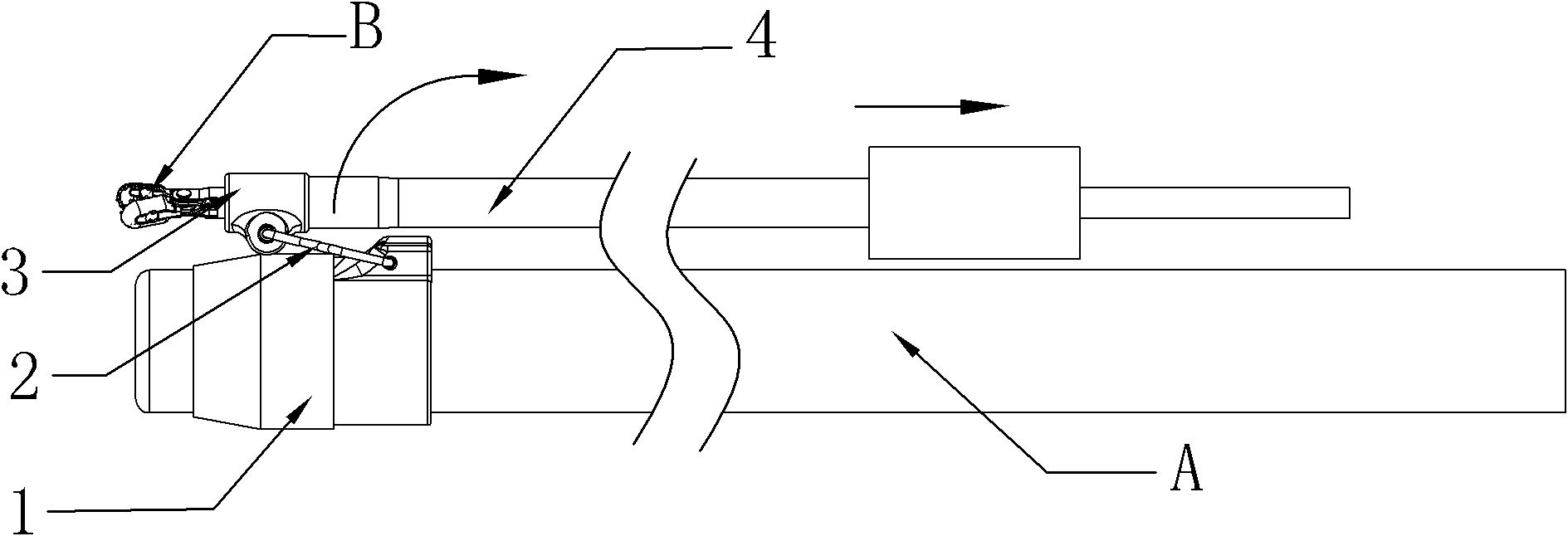
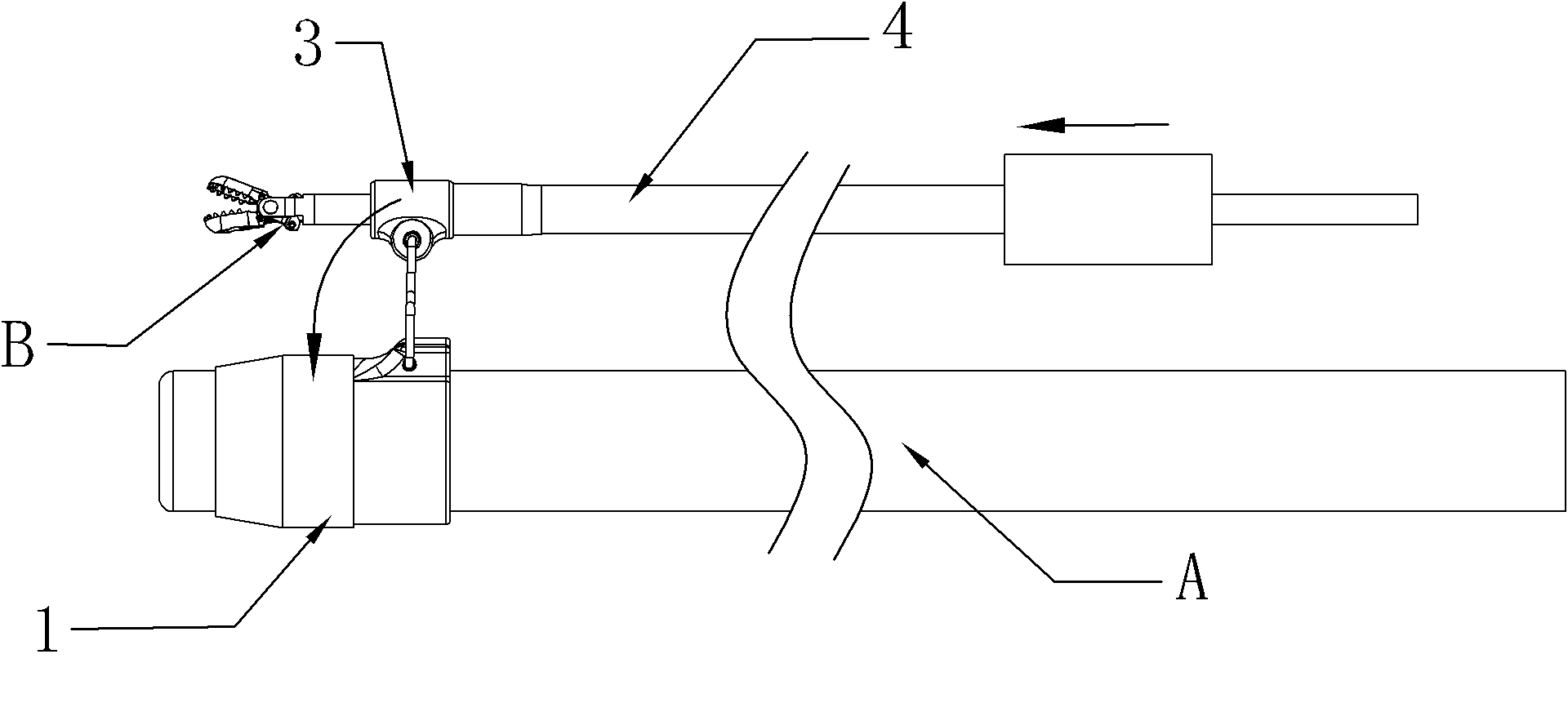
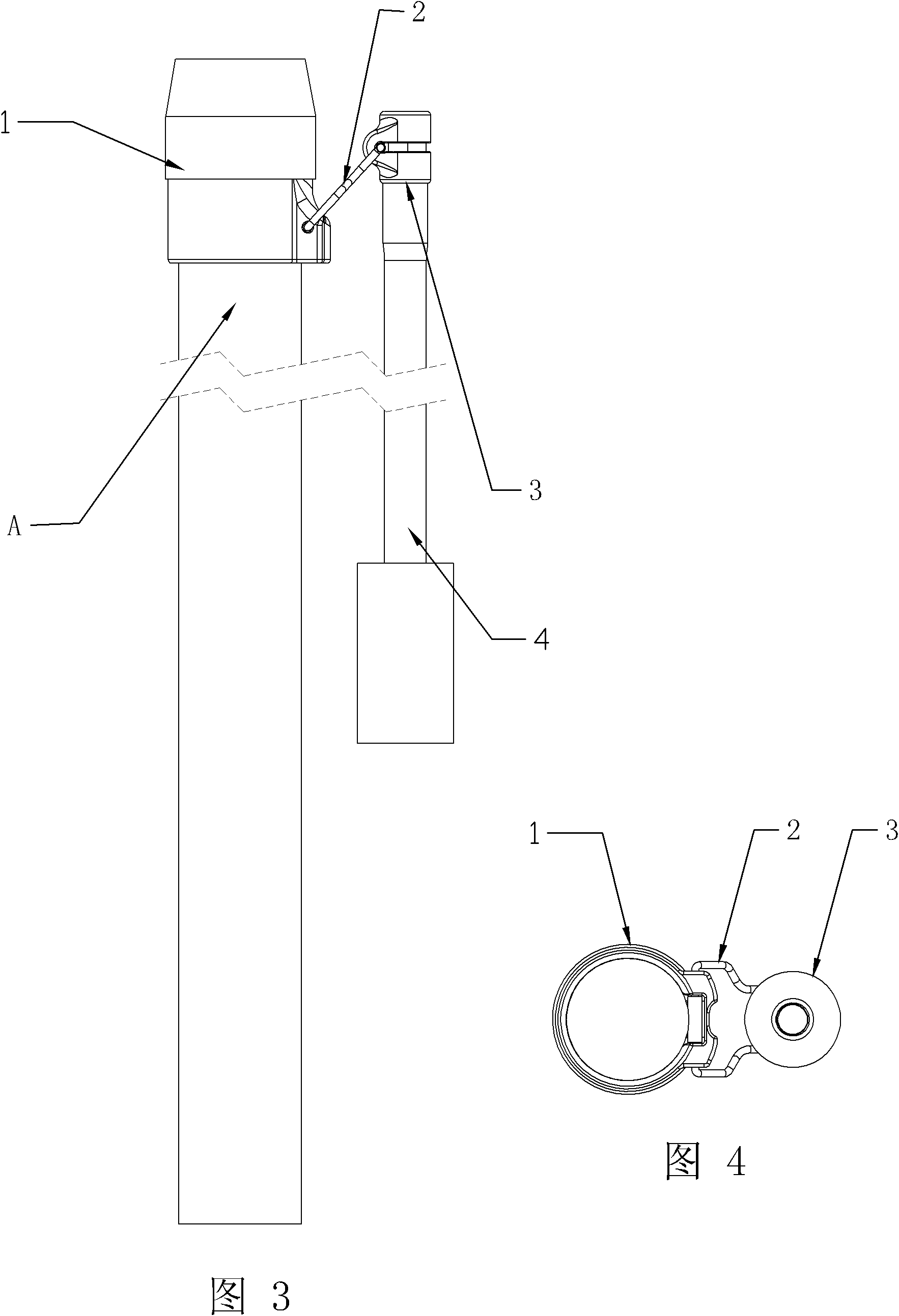
[0052] Such as image 3 , Figure 4 , Figure 5 , Figure 6 A mucosal retractor shown includes: an endoscope fixing part 1 capable of being installed on the distal head of an endoscope A; an instrument lifting part 3 capable of installing a surgical instrument B; a swing arm 2, a swing arm 2 One end is movably connected with the endoscope fixing part 1, and the other end of the swing arm 2 is movably connected with the instrument lifting part 3;

[0053] In this embodiment, the endoscope fixing part 1 forms a closed cylindrical structure and is sleeved on the outside of the distal end of the endoscope A, and the front end of the endoscope fixing part 1 is a smooth tip 6 . A closed channel is formed on the instrument lifting part 3 to allow the surgical instrument B to pass through it. The endoscope fixing part 1 , the instrument lifting part 3 , the swing arm 2 and the pulling part 4 are all made of insulating materials or have undergone insulating treatment. The traction...

Embodiment 2

[0056] Such as Figure 12 to Figure 17 A mucosal retractor shown includes: an endoscope fixing part 1 capable of being installed on the distal head of an endoscope A; an instrument lifting part 3 capable of installing a surgical instrument B; a swing arm 2, a swing arm 2 One end is movably connected with the endoscope fixing part 1, and the other end of the swing arm 2 is movably connected with the instrument lifting part 3;

[0057] In this embodiment, the endoscope fixing part 1 forms a closed cylindrical structure and is sleeved on the outside of the distal end of the endoscope A, and the front end of the endoscope fixing part 1 is a smooth tip 6 . A closed channel is formed on the instrument lifting part 3 to allow the surgical instrument B to pass through it. The endoscope fixing part 1 , the instrument lifting part 3 , the swing arm 2 and the pulling part 4 are all made of insulating materials or have undergone insulating treatment. The traction part 4 includes a tract...

Embodiment 3

[0060] Such as Figure 18 to Figure 20 A mucosal retractor shown includes: an endoscope fixing part 1 capable of being installed on the distal head of an endoscope A; an instrument lifting part 3 capable of installing a surgical instrument B; a swing arm 2, a swing arm 2 One end is movably connected with the endoscope fixing part 1, and the other end of the swing arm 2 is movably connected with the instrument lifting part 3;

[0061] In this embodiment, the endoscope fixing part 1 forms a semi-closed hoop-like structure and is sleeved on the outside of the distal end of the endoscope A, and the front end of the endoscope fixing part 1 is a smooth tip 6 . A semi-closed channel is formed on the instrument lifting part 3 to allow the surgical instrument B to pass through it. The endoscope fixing part 1 , the instrument lifting part 3 , the swing arm 2 and the pulling part 4 are all made of insulating materials or have undergone insulating treatment. The traction part 4 includes...


PUM


Abstract

The invention discloses a mucous membrane tractor comprising an endoscope fixing part, an instrument lifting part, a swinging arm and a traction part, wherein the endoscope fixing part can be installed at a distal end head of an endoscope; the instrument lifting part can be used for installing a surgical instrument; one end of the swinging arm is movably connected with the endoscope fixing part, and the other end of the swinging arm is movably connected with the instrument lifting part; and the distal end of the traction part is connected with the instrument lifting part. The technical schemeprovides endoscopic surgeons a method for controlling more instruments to be used in a matching way by utilizing the traditional endoscope, meets requirements on multiple-instruments matching operation of the surgeons to a certain extent, achieves certain effects of reducing labor intensity of the complex and time-consuming surgeries encountered currently, such as ESD (Endoscopic Submucosal Dissection) and the like, greatly shortening surgery time and improving safety and operability, facilitate popularization of some complex and time-consuming surgeries to primary hospitals and plays the role of relieving the conditions of poor access to and high cost of medical treatment at present to a certain extent.

Description

technical field [0001] The invention belongs to the technical field of medical instruments, in particular to a mucosal retractor used in endoscopic surgery that can control the position or posture of surgical instruments. Background technique [0002] Endoscopes have been used to diagnose and treat diseases for more than 50 years. Most of them are single-channel endoscopes. However, with the continuous development and improvement of endoscopic surgery techniques, a single instrument can no longer satisfy the doctor's control over the instrument. Doctors are eager to use the existing endoscope to realize that two or more instruments can cooperate with each other to adapt to complex and difficult operations, so that the operation can be completed more safely and quickly. [0003] Most of the commonly used endoscopes have only one hole for passing instruments. During the operation, it is like a person working with only one hand. There is a lack of corresponding cooperation. Som...

Claims


Application Information

Patent Timeline
Patent Type & Authority Applications(China)
IPC IPC(8): A61B17/94A61B17/02
Inventor 徐国良时百明张承单宏波
Owner 徐国良
Why Eureka
Try Eureka