
Lift control device

An elevator control device and a motor control technology, applied in the field of elevator control devices, can solve problems such as equipment failure, increased heating of the motor and inverter, and failure of the motor and inverter.

Active Publication Date: 2011-07-20
MITSUBISHI ELECTRIC CORP
View PDF1 Cites 2 Cited by
  • Summary
  • Abstract
  • Description
  • Claims
  • Application Information

AI Technical Summary

Problems solved by technology

[0004] However, in the conventional elevator control device, since the maximum speed and acceleration are changed according to the signal from the car load detection device, when the signal from the car load detection device is abnormal, the car load is erroneously identified, and the maximum speed and acceleration are erroneously identified. Acceleration increases beyond the capacity of the motor or inverter, potentially causing equipment failure
[0005] In addition, when the running loss of the car or counterweight or the mechanical loss of the traction machine is large, the motor and inverter are used beyond the capacity range because the required motor torque increases, which may cause equipment failure
[0006] Moreover, the motor and inverter are always used at the maximum capacity range, so the heat generated by the motor and inverter increases. When the elevator starts frequently, the motor and inverter may be caused by abnormal heat Fault

Method used


Image

  • Lift control device
  • Lift control device
  • Lift control device

Examples


Embodiment approach 1

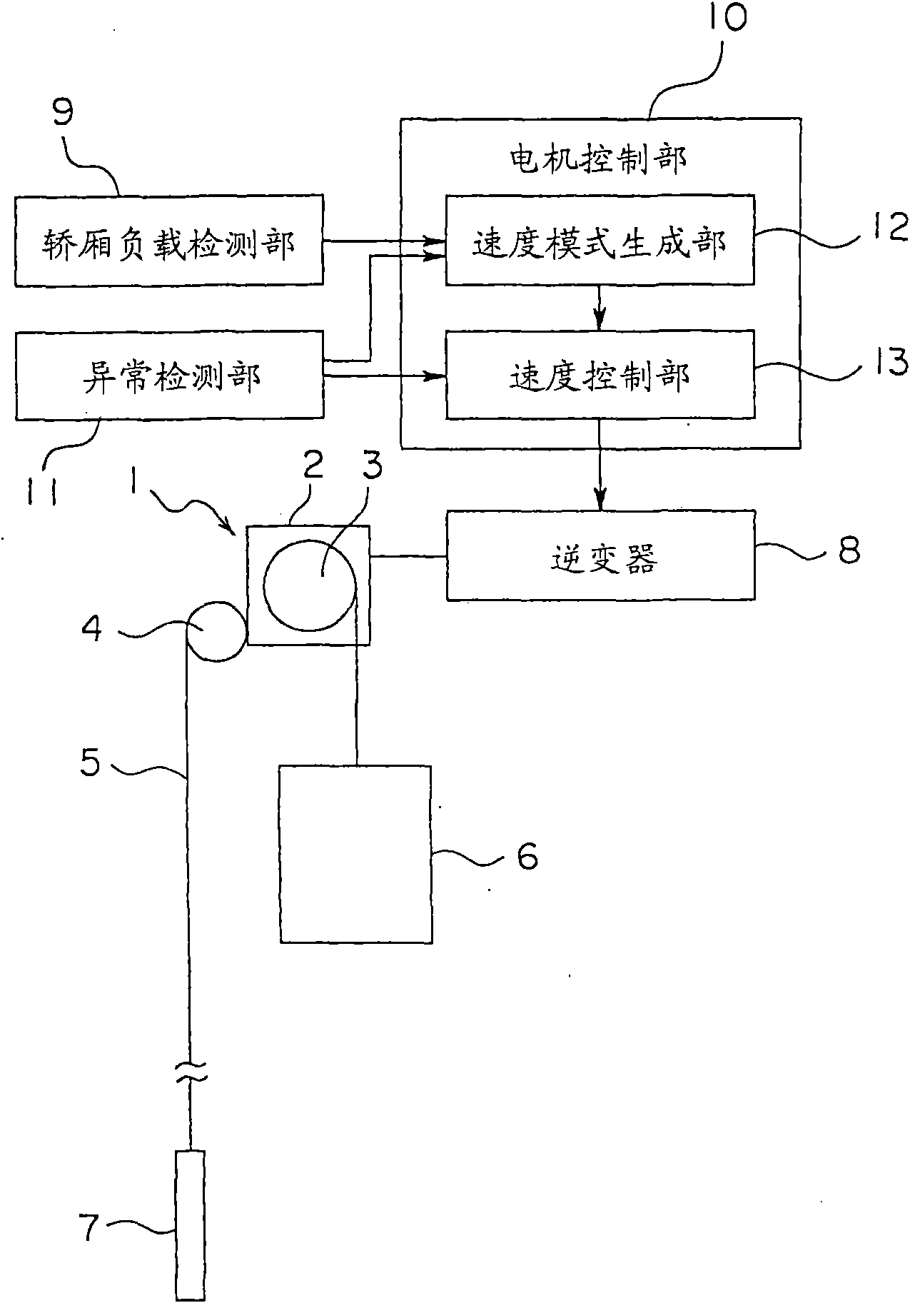
[0021] figure 1 It is a block diagram showing the elevator apparatus according to Embodiment 1 of the present invention. In the figure, a driving device (tractor) 1 is provided on the upper part of the hoistway. The traction machine 1 has a motor unit 2 and a traction sheave 3 rotated by the motor unit 2 . A braking device (not shown) for braking the rotation of the traction sheave 3 is provided in the motor unit 2 .

[0022] And, a free-rotating guide wheel 4 is provided on the top of the hoistway. A plurality of master ropes 5 (only one is shown in the figure) are wound around the traction sheave 3 and the guide sheave 4 . At one end of the main rope 5, a car 6 is suspended. A counterweight 7 is provided at the other end of the main rope 5 .

[0023] The weight of the counterweight 7 is set to be balanced when the load of the car 6 is about half of the maximum load (full load).

[0024] The operation of the motor unit 2 is driven by power supplied by the inverter 8 . ...

Embodiment approach 2

[0042] then, Figure 6 It is a block diagram showing the elevator apparatus according to Embodiment 2 of the present invention. In the figure, the temperatures of the motor unit 2 and the inverter 8 are detected by the temperature detection unit 17 . The abnormality detection part 11 is provided with the abnormality judgment part 18 which judges the abnormal state of an elevator. The abnormality determination unit 18 determines an abnormal state based on signals from the car load detection unit 9 , the speed control unit 13 , and the temperature detection unit 17 , and sends information about the abnormality to the speed pattern generation unit 12 and the speed control unit 13 . Other configurations are the same as those in Embodiment 1.

[0043] Figure 7 yes means Figure 6 An explanatory diagram of a first example of the abnormality judgment method implemented by the abnormality judgment unit 18 of . The abnormality judging part 18, for example, calculates the differen...


PUM


Abstract

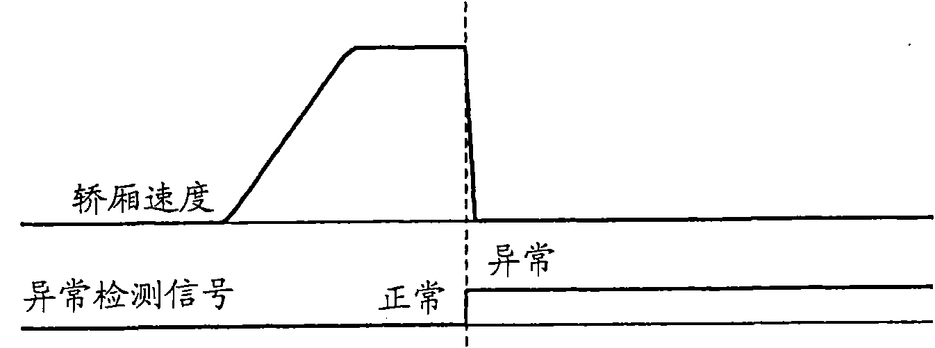
The invention provides a lift control device. In the lift control device, the maximum speed and accelerated speed of a lift car are changed according to the load capacity in the lift car. A motor control part and an abnormal detection part for detecting lift exception are arranged in the lift control device, wherein the motor control part controls a motor part to operate according to the load capacity in the lift car. When the maximum speed and accelerated speed are accelerated to allow the lift car to operate, and if the exception is detected by the abnormal detection part, the operating mode of the motor control part is changed into an abnormal mode from a general mode.

Description

[0001] This application is a divisional application of the invention patent application (application date: March 26, 2004, invention name: elevator control device) whose original application number is 200480041841.1. technical field [0002] The present invention relates to elevator controls which vary the maximum speed and acceleration of a car according to the car load. Background technique [0003] For example, in the conventional elevator control device disclosed in Japanese Unexamined Patent Application Publication No. 2003-238037, the load (hereinafter referred to as "car load") generated by the load in the car is applied to the motor and the drive motor. Within the driving range of electrical equipment, change the maximum speed and acceleration (including deceleration) of the car. As a result, the remaining power of the motor is effectively utilized, and the operating efficiency of the car is improved. [0004] However, in the conventional elevator control device, si...

Claims


Application Information

Patent Timeline
IPC IPC(8): B66B1/30B66B5/02
Inventor 仮屋佳孝酒井雅也上田隆美
Owner MITSUBISHI ELECTRIC CORP
Learn More