Rotational speed reducer

a technology of rotational speed reducer and speed reducer, which is applied in the direction of driving belts, toothed gearings, gearings, etc., can solve the problems of mechanical power being transferred, speed reducers subject to failures, and speed reducers to be worn to a greater extent, so as to reduce the number of components used, the overall dimension of the speed reducer is reduced, and the speed reducer is more efficient

Active Publication Date: 2020-01-21
FOND INST ITAL DI TECH +1
View PDF16 Cites 2 Cited by
  • Summary
  • Abstract
  • Description
  • Claims
  • Application Information

AI Technical Summary

Benefits of technology

[0012]In particular it is an object of the present invention to provide a compact epicyclic speed reducer.
[0013]It is also an object of the present invention to provide an epicyclic speed reducer with high efficiency and noiselessness properties.
[0024]Such solution allows overall dimensions of an epicyclic speed reducer to be reduced while obtaining a compact speed reducer miniaturizable both in the radial and axial directions, due to the reduced number of components used and to their arrangement coaxial with the axis of the rotational motion passing through the speed reducer.
[0025]Moreover the greater simplicity in transmitting the motion allows a speed reducer more efficient and rotationally balanced to be obtained. Such better balancing and the reduced number of components causes vibrations during its operation to be reduced, and therefore it allows the value of the allowable maximum speed of the driving shaft to be increased.
[0026]Moreover the use of belts further improves the efficiency of the speed reducer since it allows power to be transmitted more fluidly, progressively and with a low noise, while allowing impacts and sudden changes of the load to be absorbed, protecting motors and supports connected thereto.

Problems solved by technology

The solution known from U.S. Pat. No. 2,956,451 has the drawback that the use only of gears makes the speed reducer subject to failures due to impulse torques, for example resulting from impacts, which act on the driven shaft therefore causing the speed reducer to be worn to a greater extent.
Moreover such solution does not allow mechanical power to be transferred in a fluid and progressive manner and its operation generates a high noise due to metal couplings transmitting the motion.
The solution known from U.S. Pat. No. 4,919,011 on the contrary has the drawback that the contacts between gears are guaranteed only by the friction between two metal surfaces, and this leads to high overheating and it reduces both the life cycle of the speed reducer and the torque that can be transmitted.
Such arrangement however determines great overall dimensions both in the radial direction and in the axial direction of the speed reducer, and it invalidates the efficiency of the system due to mechanical losses resulting from the high number of components of the kinematic chain.
Moreover such a complicated system is subjected to higher frictions, it runs the risk of being unbalanced and of generating vibrations that allow it to be used only under moderate speeds.

Method used


Image

  • Rotational speed reducer
  • Rotational speed reducer
  • Rotational speed reducer

Examples


Embodiment Construction

[0035]While the invention is susceptible of various modifications and alternative forms, some non-limitative embodiments, given by way of example, are described herein below in details.

[0036]It should be understood, however, that there is no intention to limit the invention to the specific embodiments disclosed, but, on the contrary, the intention of the invention is to cover all modifications, alternative constructions and equivalents falling within the scope of the invention as defined in the claims.

[0037]Therefore, in the description below, the use of “for example”, “etc”, “or” indicates non-exclusive alternatives without limitation unless otherwise defined; the use of “also” means “among which, but not limited to”, unless otherwise defined; the use of “include / comprise” means “include / comprise, but not limited to,” unless otherwise defined.

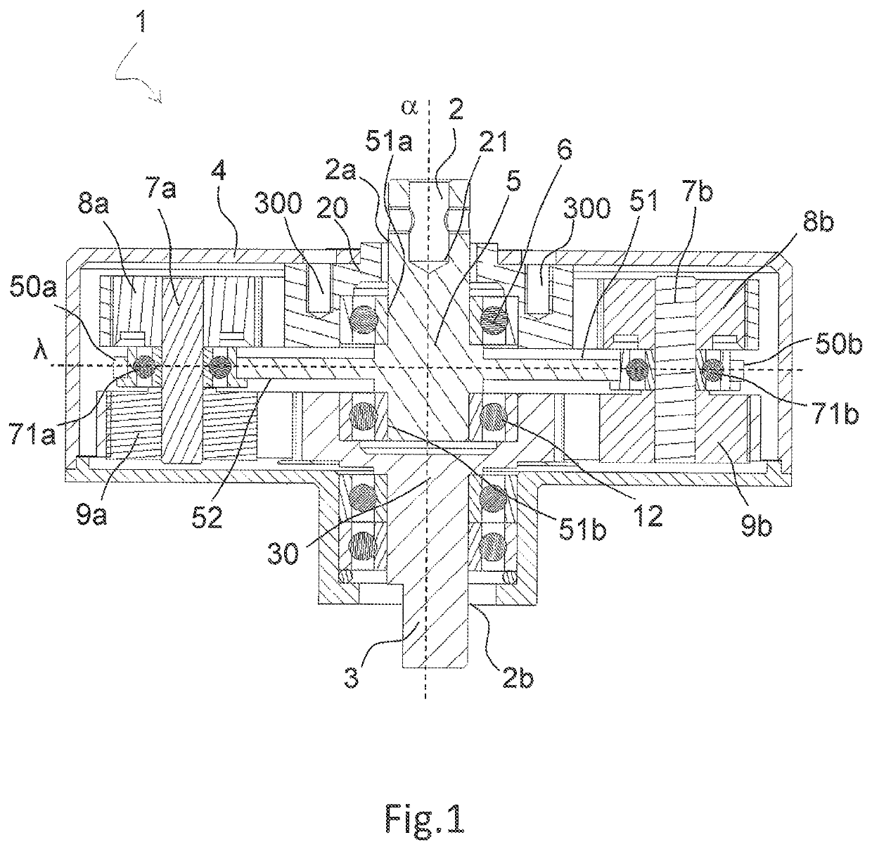
[0038]FIG. 1 is a section of a top view of an epicyclic speed reducer, denoted by reference numeral 1, to transmit a rotational motion from o...


PUM


Abstract

The present invention relates to an epicyclic speed reducer (1), comprising a casing (4) comprising a first (2a) and a second opening (2b) arranged on opposite faces of said casing (4). The casing (4) houses inside it: a first sun gear (20) fastened inside the casing (4) at said first opening (2a); a second sun gear (30) coaxial with the first sun gear (20) with the axis passing from the first opening (2a) to the second opening (2b); a first planet gear (8a, 8b) adapted to describe a circular orbit around the first sun gear (20); a second planet gear (9a, 9b) adapted to describe a circular orbit around the second sun gear (30); a supporting element (5) interposed between the first (20) and second (30) sun gear and adapted to rotate around the axis, the supporting element (5) connected to the first (8a, 8b) and second (9a, 9b) planet gear in such a way as to allow a relative rotation of the supporting element (5) with respect to the first (8a, 8b) and second (9a, 9b) planet gear; a first belt (10) connected to the first planet gear (8a, 8b) and to the first sun gear (20); a second belt (11) connected to the second planet gear (9a, 9b) and to the second sun gear (30). Moreover the supporting element (5) is provided with a seat (21) coaxial with the axis and adapted to be fitted on one end (2) of a driving shaft such that when the seat is fitted on the driving shaft the supporting element (5) and the driving shaft are rigidly connected.

Description

TECHNICAL FIELD[0001]The present invention relates to the field of motion transmitting mechanisms, particularly of the type used for reducing angular velocity.[0002]The present invention particularly relates to epicyclic speed reducers according to the preamble of claim 1.PRIOR ART[0003]The epicyclic speed reducer is a mechanism able to transmit a rotational motion from a driving shaft to a driven shaft while reducing rotational angular velocity.[0004]Generally the speed reducer comprises a sun gear and one or more planet gears rotating about it. Planet gears generally are mounted on a structure, called as arm or planet carrier, free to rotate at a speed different from that of the sun gear or of the driving shaft.[0005]Epicyclic gear trains are currently known having different configurations that allow the motion of the driving shaft to be transferred, while being reduced, to the driven shaft.[0006]For example U.S. Pat. Nos. 2,956,451 and 4,919,011 disclose an epicylic transmitting ...

Claims


Application Information

Patent Timeline
Patent Type & Authority Patents(United States)
IPC IPC(8): F16H1/46F16H7/02F16H9/26F02B67/06F16G1/28F16H57/08F16H1/28F16H7/08
CPCF16H57/082F16H7/02F16H9/26F16H7/023F02B67/06F16H1/46F16G1/28F16H2007/0865F16H2001/2881F05B2260/40311
Inventor BIBOLOTTI, ALBERTO
Owner FOND INST ITAL DI TECH
Why Eureka
Try Eureka