Hydraulic arrangement for supplying a consumer

A technology of a hydraulic device and a locking device, applied in the field of hydraulic devices, can solve problems such as restricted flow, and achieve the effect of increasing the maximum speed and the best energy efficiency

Active Publication Date: 2015-03-18
ROBERT BOSCH GMBH
View PDF8 Cites 2 Cited by
  • Summary
  • Abstract
  • Description
  • Claims
  • Application Information

AI Technical Summary

Problems solved by technology

[0005] The disadvantage of this arrangement is the restricted flow rate which is obtained by the series or series connection of the pumps or switching valves

Method used


Image

  • Hydraulic arrangement for supplying a consumer
  • Hydraulic arrangement for supplying a consumer
  • Hydraulic arrangement for supplying a consumer

Examples


Embodiment Construction

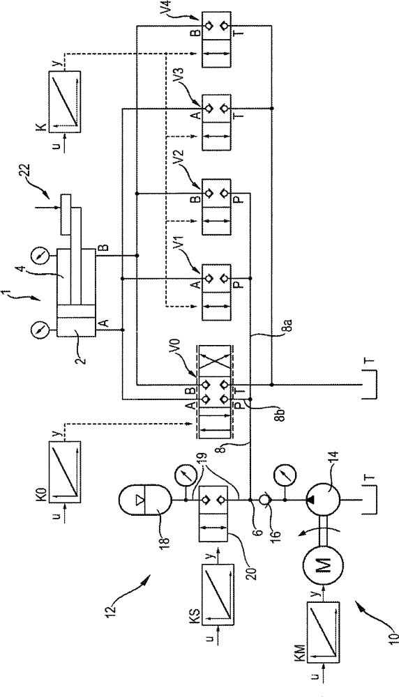
[0064] attached figure 1 A first exemplary embodiment of a device according to the invention for supplying a differential cylinder 1 is shown. The piston base space 2 of the differential cylinder is connected to the first working port A, while the annular chamber 4 is connected to the second working port B. Since the piston of the differential cylinder 1 can be moved in both directions by a corresponding supply of pressure medium, the two input-side 2 / 2-way switching valves (2 / 2 switching valves) V1, V2 The two output-side 2 / 2-way switching valves V3 , V4 are connected to the corresponding working ports A, B of the differential cylinder 1 . The two feed-side 2 / 2-way switching valves V1 , V2 are connected to the node 6 via a common feed line 8 and via a first feed line 8 a. The two outlet-side 2 / 2-way switching valves V3 , V4 are connected to tank T. The four 2 / 2-way switching valves V1 , V2 , V3 , V4 are assigned to the first supply device 10 and open when the first supply ...


PUM


Abstract

A hydraulic arrangement for supplying a consumer or actuator includes a first supply device that has at least one pump with an adjustable delivery volume. The hydraulic arrangement further includes a second supply device that is connected in parallel to the first supply device. The second supply device includes a loadable accumulator and a digitally regulated switching valve arrangement.

Description

technical field [0001] The invention relates to a hydraulic device for supplying loads or actuators according to the preamble of claim 1 . Background technique [0002] According to the background art, pumps with adjustable delivery rates are also used to supply loads (eg cylinders or motors) whose speed (eg travel speed or rotational speed) is to be adjustable or controllable. In this context, a first basic principle is already known, in which the rotational speed of a metering pump can be varied by means of an adjustable electric motor. According to a second basic principle, the delivery rate of a constantly driven regulating pump can be varied by means of an regulating device of the regulating pump. In this case, the displacement volume, which adjusts the geometry of the pump, will be changed. For example, the stroke of the piston of the regulating pump is changed, which piston executes the stroke during the rotation of its rotor. By means of different delivery rates (...

Claims


Application Information

Patent Timeline
Patent Type & Authority Applications(China)
IPC IPC(8): F15B11/04F15B1/033F15B11/08
CPCF16H61/4008F16H61/4061F16H61/4096F15B11/04F15B1/024F15B11/0426F15B2211/7656F15B2211/665F15B2211/6336F15B2211/20538F15B2211/20515F15B2211/212F15B2211/30565F15B2211/427F15B2211/40592F15B2211/328
Inventor G·亨德里克斯H·梅林A·科克曼
Owner ROBERT BOSCH GMBH
Why Eureka
Try Eureka