Light guide plate

A light guide plate and light incident surface technology, which is applied in the field of light guide plates, can solve the problems of uneven light output from the light guide plate, achieve uniform light output, and improve the effect of uneven brightness and darkness

Inactive Publication Date: 2011-07-20
INNOCOM TECH SHENZHEN +1
View PDF0 Cites 14 Cited by
  • Summary
  • Abstract
  • Description
  • Claims
  • Application Information

AI Technical Summary

Problems solved by technology

[0005] In order to solve the problem of uneven light output from the light guide plate i

Method used


Image

  • Light guide plate
  • Light guide plate
  • Light guide plate

Examples


Example Embodiment

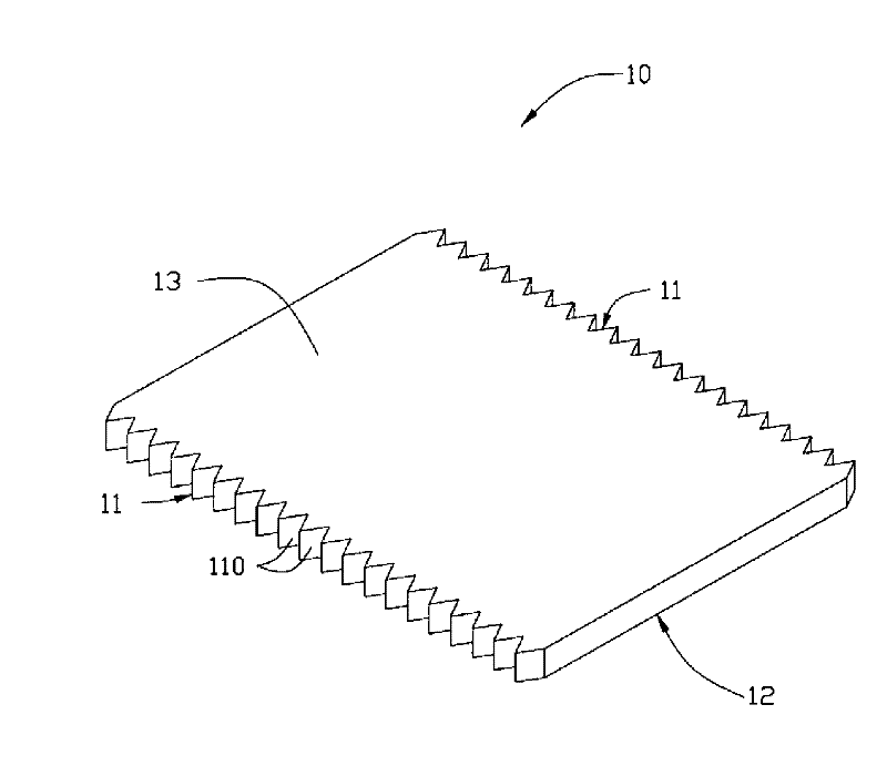
[0022] see figure 1 , which is a schematic perspective view of the first embodiment of the light guide plate of the present invention. The light guide plate 10 includes two opposite light incident surfaces 11 , a bottom surface 12 connected to the two light incident surfaces 11 , and a light exit surface 13 connected to the two light incident surfaces 11 and opposite to the bottom surface. The two light-incident surfaces 11 include a plurality of groove-shaped microstructures 110 , and the extending direction of the groove-shaped microstructures 110 is perpendicular to the bottom surface 12 and the light-emitting surface 13 . The groove-shaped microstructure is continuously distributed V-shaped grooves.

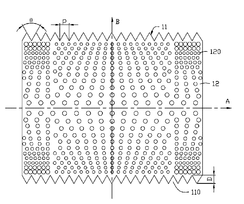
[0023] Please also refer to figure 2 , which is a schematic plan view of the bottom surface 12 of the light guide plate 10 . Wherein, the apex angle θ=60±5° and the depth D=40±15 μm of each groove-shaped microstructure 110 . The distance between two adjacent groove-shape...


PUM

PropertyMeasurementUnit
Minimum diameteraaaaaaaaaa
The maximum diameteraaaaaaaaaa

Abstract

The invention relates to a light guide plate, comprising two opposite light-incident surfaces, a bottom surface and a light-emergent surface, wherein the bottom surface is connected with the two light-incident surfaces; the light-emergent surface is connected with the two light-incident surfaces and is opposite to the bottom surface; the bottom surface comprises a plurality of mesh points. From the two sides where the light-incident surfaces are arranged to the central position, the density of the mesh points positioned at the main part of the bottom surface is reduced gradually while the diameter is increased gradually. The light guide plate has good light-emergent uniformity.

Description

technical field [0001] The invention relates to a light guide plate, in particular to a light guide plate used in a display backlight module. Background technique [0002] Liquid crystal display devices have been widely used in mobile phones, personal digital assistants, notebook computers, personal computers, and televisions due to their low radiation, small size, and low power consumption. Since the liquid crystal panel itself of the liquid crystal display device does not have light-emitting characteristics, in order to achieve the display effect, it is necessary to provide the liquid crystal panel with a backlight module to provide the liquid crystal panel with sufficient brightness and evenly distributed plane light, thereby realizing the display of the liquid crystal display device. Function. [0003] The backlight module mainly includes a light guide plate, a light source, a reflector and one or more optical films. The light source is generally a point light source o...

Claims


Application Information

Patent Timeline
IPC IPC(8): F21V8/00G02F1/13357
Inventor 张献文
Owner INNOCOM TECH SHENZHEN
Why Eureka
Try Eureka