
Light emitting assembly, backlight module and liquid crystal display

A technology of a light-emitting component and a backlight module, which is applied to semiconductor devices of light-emitting components, optical components, instruments, etc., and can solve problems such as uneven brightness and darkness of the backlight module, reduced luminous efficacy of the light-emitting component 1a, and reduced luminous efficacy of the light-emitting component 1b, etc. To achieve the effect of improving luminous efficacy, improving uneven brightness and darkness, and high luminous efficacy

Inactive Publication Date: 2015-07-01
INNOLUX CORP
View PDF5 Cites 0 Cited by
  • Summary
  • Abstract
  • Description
  • Claims
  • Application Information

AI Technical Summary

Problems solved by technology

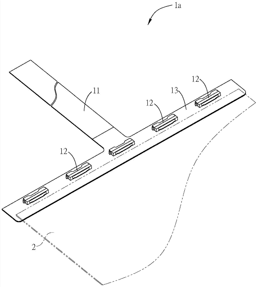
[0006] However, if Figure 1A As shown in the light-emitting assembly 1a of the light-emitting assembly 1a, when the light-emitting units 12 emit light, part of the light will be refracted on the adhesive tape 13 and absorbed by the adhesive tape 13 before entering the light guide plate 2, so that the overall luminous efficacy of the light-emitting assembly 1a is reduced.
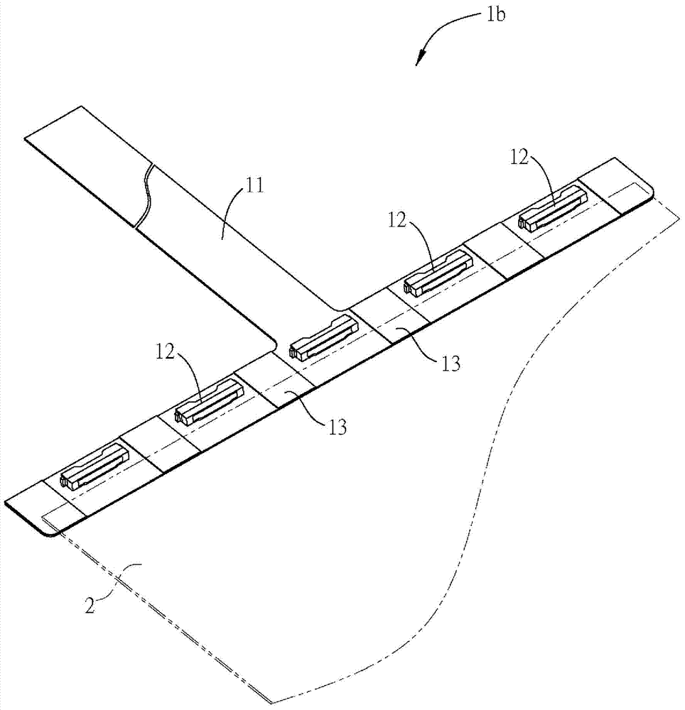
Additionally, if Figure 1B As shown in the light-emitting component 1b of the light-emitting component 1b, part of the light will also be refracted on the flexible board 11 and absorbed by the flexible board 11 before entering the light guide plate 2, so that the overall luminous efficacy of the light-emitting component 1b will also be reduced.
In addition, regardless of the design of the light-emitting component 1a or the light-emitting component 1b, it may also cause uneven brightness and darkness in the backlight module, which will affect the luminous efficacy of the overall backlight module.

Method used


Image

  • Light emitting assembly, backlight module and liquid crystal display
  • Light emitting assembly, backlight module and liquid crystal display
  • Light emitting assembly, backlight module and liquid crystal display

Examples


Embodiment Construction

[0050] In order to have a clearer understanding of the technical features, purposes and effects of the present invention, the specific implementation manners of the present invention will now be described with reference to the accompanying drawings.

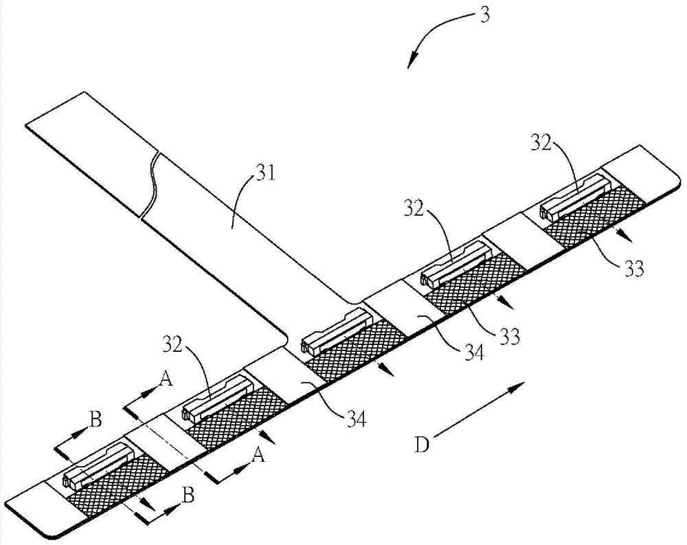
[0051] Please refer to Figure 2A to Figure 2E As shown, among them, Figure 2A It is a three-dimensional schematic diagram of a light-emitting component 3 in a preferred embodiment of the present invention, Figure 2B for Figure 2A , the schematic cross-sectional view of line A-A, Figure 2C for Figure 2A , the schematic cross-sectional view of the line B-B, Figure 2D for Figure 2A The partially enlarged schematic diagram of the light-emitting component 3, and Figure 2E for Figure 2A A schematic partial top view of the light-emitting assembly 3 of FIG. The light-emitting component 3 can be applied, for example but not limited, to a light-emitting source of a side-mounted backlight module of a flat-panel display dev...


PUM


Abstract

The invention relates to a light emitting assembly, a backlight module and a liquid crystal display. The light emitting assembly is used for transmitting light rays into a light guide plate and comprises a substrate, a plurality of light emitting units and a light path adjusting layer. The light emitting units are arrayed on the substrate along a direction. The light path adjusting layer is arranged on the substrate, corresponds to the light emitting units and is provided with a plurality of microstructures, and the various microstructures are positioned on light paths of the light rays which are emitted by the various light emitting units towards the light guide plate. The light emitting assembly, the backlight module and the liquid crystal display have the advantage that the light emitting efficiency can be improved.

Description

technical field [0001] The invention relates to a light-emitting component, a backlight module and a liquid crystal display, in particular to a light-emitting component with a light-emitting diode, a backlight module and a liquid crystal display. Background technique [0002] In recent years, due to continuous improvements in technology and materials of light emitting diodes (Light Emitting Diodes, LEDs), the luminous efficiency of light emitting diodes has been greatly improved. Different from ordinary fluorescent lamps or energy-saving bulbs, LEDs have the characteristics of low power consumption, long service life, high safety, short luminous response time and small size, so they are gradually used in lighting equipment, such as indoor lamps and flashlights , headlights of automobiles and motorcycles and other lighting devices, or used in backlight modules of flat-panel display devices. [0003] Taking a side-mounted backlight module applied to a flat panel display devic...

Claims


Application Information

Patent Timeline
Patent Type & Authority Applications(China)
IPC IPC(8): F21V17/00G02F1/13357F21Y101/02F21Y103/10F21Y115/10
CPCG02B6/0038G02B6/004G02B6/0068G02F1/133615G02F1/133607
Inventor 何文魁
Owner INNOLUX CORP
Learn More