Sealed lubricator of enameling machine

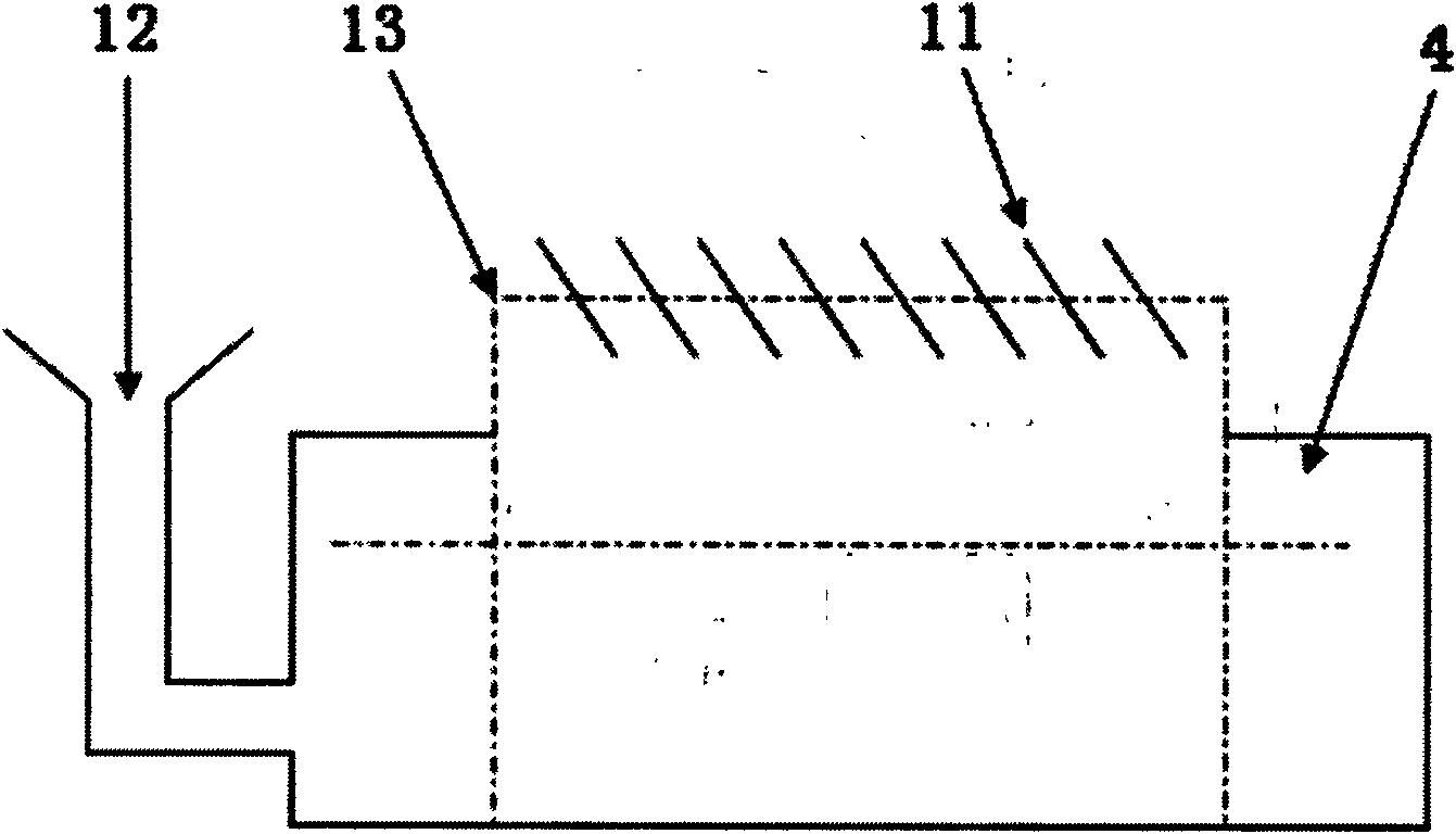
A sealed and enamelled machine technology, applied to electrical components, circuits, conductor/cable insulation, etc., can solve the problems of uneven liquid level, small and large oil absorption of oiled felt 13, etc.

Inactive Publication Date: 2011-07-20
山东蓬泰股份有限公司
View PDF5 Cites 8 Cited by
  • Summary
  • Abstract
  • Description
  • Claims
  • Application Information

AI Technical Summary

Problems solved by technology

Its shortcoming has: 1), oil amount is added in the lubricating oil box 4 by hand, and liquid level is uneven
2) When the liquid level in the oil box 4 is high, the oil absorption capacity of the oil-coated felt 13 is large, and when the liquid level is low, the oil absorption capacity of the oil-coated felt 13 is small, and the coating line is uneven
3) The part of the oiled felt 13 higher than the oil box has no seal and is easy to volatilize
4), the lubricating oil in the oiled felt 13 is in contact with the air, and the solvent volatilizes in the air, polluting the production environment

Method used


Image

  • Sealed lubricator of enameling machine
  • Sealed lubricator of enameling machine
  • Sealed lubricator of enameling machine

Examples


Embodiment 1

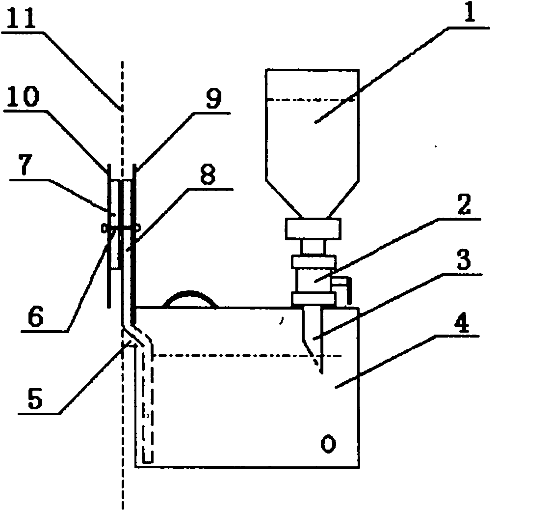
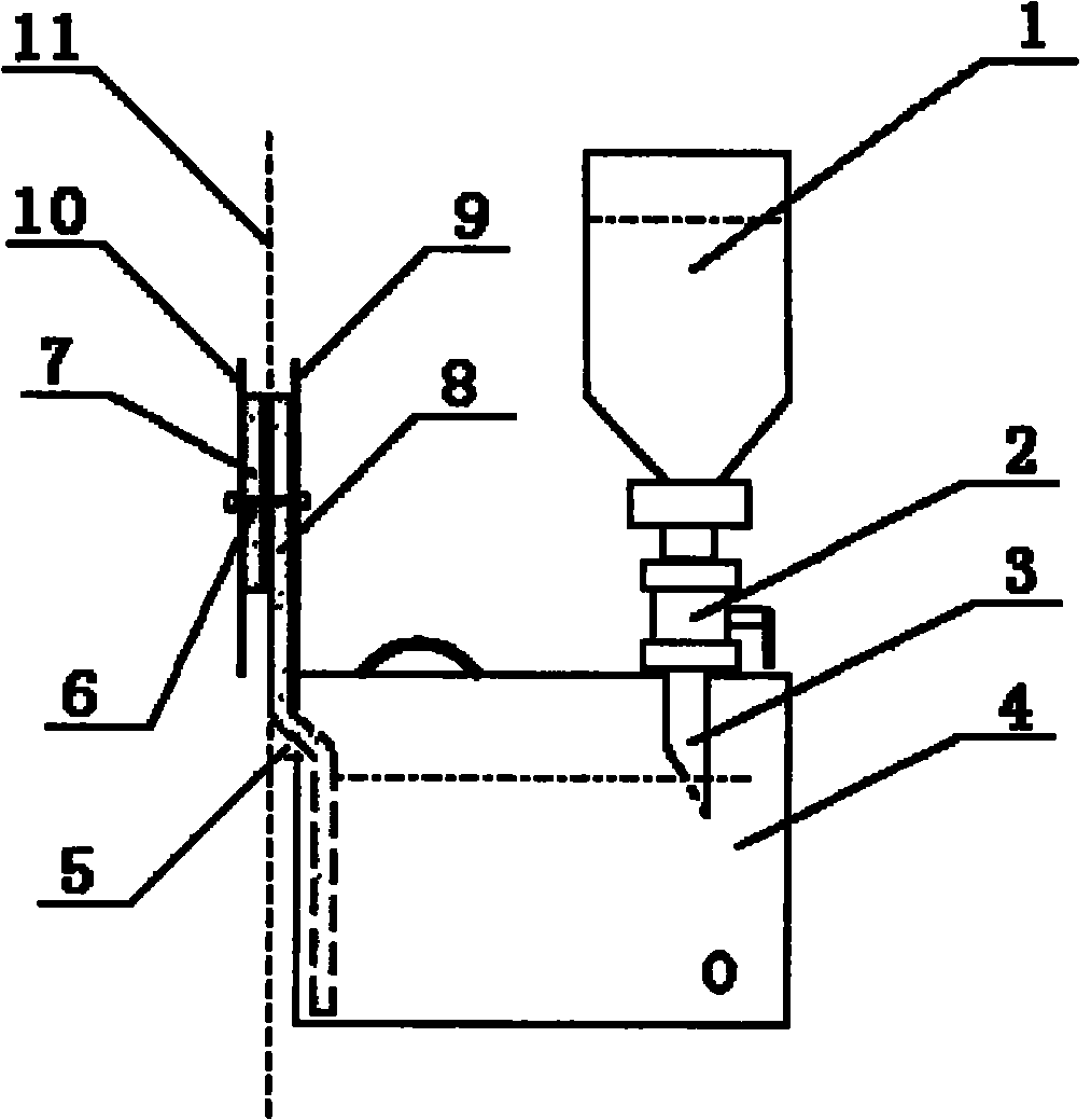
[0017] The sealed oiler of enamelling machine has a structural feature that a control valve 2 is installed on the mouth of the oil cup 1, and the other end of the control valve 2 is connected with an oil outlet pipe 3, and the oil outlet pipe 3 is inserted into the oil inlet opened on the oil box 4, Oil box 4 is refueled from oil cup 1 on the top, and the oil level of oil box 4 can automatically control the liquid level height due to the combined action of gravity and atmospheric pressure; one side of oil box 4 is equipped with a felt fixing splint 9, and the felt fixing splint 9 There is a felt hole 5 on the side of the oil box 4 at the lower end, the lower edge of the felt hole 5 is higher than the outlet of the oil outlet pipe 3, and a part of the first felt 7 and the second felt 8 are installed on the surface of the first felt 7 and a part of the second felt 8 and fixed on the felt fixing splint through the fixing column 6 Between 9 and the pressure plate 10, a felt groove ...

Embodiment 2

[0019] The difference between this embodiment and embodiment 1 is that

[0020] The outlet of the oil outlet pipe 3 is an oblique opening, and the lower edge of the felt hole 5 is higher than the upper edge of the oblique opening of the oil outlet pipe 3 .

[0021] The function of the control valve 2 installed on the mouth of the oil cup 1 is to close the control valve 2 to limit the flow of lubricating oil in the oil cup 1 when the oil cup 1 is refueled or inserted into the oil inlet of the oil box 4.

[0022] When adding lubricating oil to the sealed oiler of the enamelling machine, first close the control valve 2, take out the oil cup 1, control valve 2, and oil outlet pipe 3 from the oil box 4, separate the oil cup 1 from the control valve 2, and lubricate Put the oil into the oil cup 1, then connect the control valve 2 to the interface of the oil cup 1, then insert it into the oil inlet on the oil box 4, and open the control valve 2.


PUM


Abstract

The invention relates to a sealed lubricator of an enameling machine and belongs to the technical field of the structures of lubricators. The sealed lubricator of the enameling machine is characterized in that: a control valve is installed on a cup mouth of an oil cup; an oil output pipe is connected to the other end of the control valve, and is inserted in an oil inlet on an oil box which is refueled through the oil cup at the top part; a felt fixing clamping plate is arranged at the upper end of one side of the oil box; a felt hole is arranged at the side face of the oil box at the lower end of the felt fixing clamping plate; parts of a first felt and a second felt are installed between the felt fixing clamping plate and a pressing plate in an adhering manner; a part of the second felt enters the oil box through the felt hole; lubricating oil permeates to the upper part of the second felt through the part of second felt stretched into the oil box; and an enameled wire penetrates through the two felts, so that the coating of the lubricating oil on the surface of the enameled wire is realized. The sealed lubricator has the advantages of reasonable design, fixed height of the liquid level in the oil box, uniform oil absorption of felts, no volatilization and waste of the lubrication oil and no pollution to the production environment. As the enameled wire penetrates through the two felts, the coating is more uniform.

Description

1. Technical field [0001] The invention relates to a sealed oiler for an enameling machine, in particular to an oiler suitable for the enameled wire industry, and belongs to the technical field of oiler structures. 2. Background technology [0002] At present, in the enameled wire production process, the enameled wire surface lubricating oil coating of the enameled machine equipment is coated by the felt method, and the lubricating oil in the oil box is absorbed by the felt. When the enameled wire passes through the surface of the felt, the lubricating oil adheres to the surface of the enameled wire to complete Coating, and then collected in the enameled wire reel. [0003] figure 2 Shown is the lubricating oil coating device in the prior art. [0004] Lubricating oil is added by filling hole 12, and oiling mode is that felt 13 absorbs the lubricating oil in the oil box 4, and enameled wire 11 finishes coating through oiling felt 13 surfaces. Its shortcoming has: 1), oil ...

Claims


Application Information

Patent Timeline
Patent Type & Authority Applications(China)
IPC IPC(8): H01B13/00H01B13/16
Inventor 迟力夫梁守卫
Owner 山东蓬泰股份有限公司
Why Eureka
Try Eureka