Self-seeded single-frequency solid-state ring laser and system using same

a single-frequency solid-state ring laser and self-seeded technology, which is applied in the direction of substation equipment, manufacturing tools, welding/soldering/cutting articles, etc., can solve the problems of limited mopa configuration performance, inability to provide lasers with both sufficient energy and sufficient repetition rate to achieve production throughput at affordable costs, and inability to use. , to achieve the effect of reducing the number of pulses, and reducing the number of laser

Active Publication Date: 2007-02-20
METAL IMPROVEMENT CO INC +1
View PDF63 Cites 7 Cited by
  • Summary
  • Abstract
  • Description
  • Claims
  • Application Information

AI Technical Summary

Benefits of technology

[0014]The present invention provides a self-seeded laser oscillator having simple design, and capable of providing as much as 10 times greater energy and 10 times lesser pulse duration than demonstrated using the approach of U.S. Pat. No. 5,022,033. The self-seeded laser oscillator is applied in laser systems having a master oscillator / power amplifier configurations in some embodiments of the invention. In addition, an improved laser peening system and an improved laser peening process are provided based upon sequences of pulses produced according to the present invention that have substantially constant pulse heights and pulse widths without operator intervention over intervals of time that are significant in a production setting.
[0015]One embodiment of the invention is a method of operating a laser to obtain an output pulse having a single wavelength. The laser includes a resonator, an output coupler and a gain medium positioned inside the resonator and a pump source. The method comprises inducing an intracavity loss into laser resonator, such as by insertion of a polarization rotation element inside the resonator, rotating polarization slightly off a polarization which is transmitted by an output coupler implemented using a polarization beam splitter. The loss established has an amount that prevents oscillation during a time that energy from the pump source is being stored in the gain medium. Gain is built up in the gain medium with energy from the pump source until a point that the stored gain overcomes the induced loss to produce a seed pulse. The gain overcomes the loss at a point when a ratio of gain to loss is established that results in formation of a single-frequency relaxation oscillation pulse in the resonator.
[0016]Upon detection of the relaxation oscillation pulse, the intracavity loss is reduced, such as by Q-switching by electronically controlling the Pockels cell, so that the built-up gain stored in the gain medium is output from the resonator in the form of an output pulse at a single frequency.
[0018]The laser oscillator is further optimized by controlling the reflectivity of the resonator output coupler. The choice of reflectivity of the output coupler has a significant impact on the Q-switched pulse duration and output power extraction efficiency. Conventionally, this can only be achieved by optical coatings with differing reflectivities. In the resonator presented here, the output coupler is implemented using a polarizing beam splitter. The effective output coupling of the resonator is dependent on the polarization of the beam in the resonator, established by polarizing elements in the resonator, and in response to pulsed voltage applied to the Pockels cell during the Q-switching. This can be readily optimized by setting polarization components in the resonator, and electronically controlling the pulsed voltage to achieve a desirable Q-switched pulse duration.
[0021]In some embodiments of the invention, the Q-switch comprises a Pockels cell and the output coupler comprises a polarizing beam splitter. A quarter wave plate rotated slightly to induce slightly elliptical polarization at the output coupler induces loss, while allowing a slight amount of light to circulate in the resonator. The controller decreases loss in the resonator by controlling a voltage applied to the Pockels cell. During Q-switching, a voltage pulse is applied to decrease loss in the resonator. By setting the magnitude of the voltage pulse applied during Q-switching, the reflectivity of the output coupler is established at a level chosen to set a desired pulse duration.

Problems solved by technology

However, for many applications, shot peening does not provide sufficiently intense or deep treatment or cannot be used because of its detrimental effect on the surface finish.
However, lasers with both sufficient energy and sufficient repetition rate to achieve production throughput at affordable costs have been difficult to provide.
The performance of the MOPA configuration is limited to a degree by the quality of the seed pulse provided by the master oscillator.
However, it has been difficult to maintain the pulse width and pulse energy substantially constant in a production environment at a sufficient pulse energies.
However, this technique requires careful mode matching between the master and slave oscillators and active cavity length stabilization for the Q-switched slave oscillator.
Thus, the consistency of pulse parameters is relatively poor, and for laser peening operations with output pulses as consistent as possible, it would be necessary to constantly adjust optical parameters of the seed oscillator, such as flashlamp energy and the like.
One primary disadvantage of this approach is the long pulse durations (200 ns) and low pulse energies that result from the inefficiencies of keeping a constant, CW seed oscillation running between pulses.

Method used


Image

  • Self-seeded single-frequency solid-state ring laser and system using same
  • Self-seeded single-frequency solid-state ring laser and system using same
  • Self-seeded single-frequency solid-state ring laser and system using same

Examples


Embodiment Construction

[0036]A detailed description of embodiments of the present invention is provided with reference to FIGS. 1–8. A self-seeded single-frequency solid-state Q-switched ring laser with electronically adjustable output coupling is described with reference to FIGS. 1–5. FIG. 7 illustrates a master oscillator / power amplifier embodiment of the present invention including the laser system of FIGS. 1–5 as a master oscillator, capable of producing pulses as graphed in FIG. 6. FIG. 8 illustrates application of the present invention in a laser peening environment.

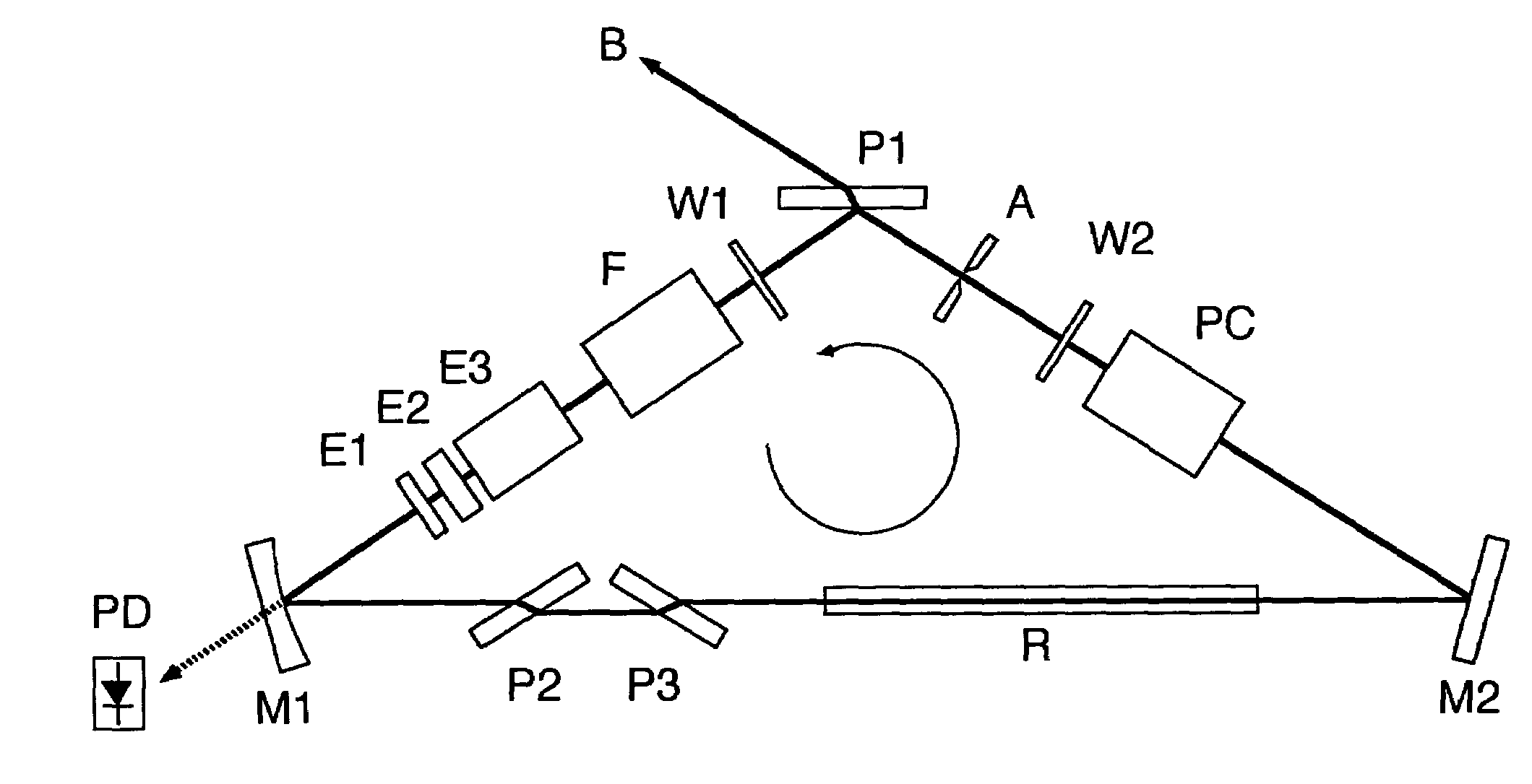
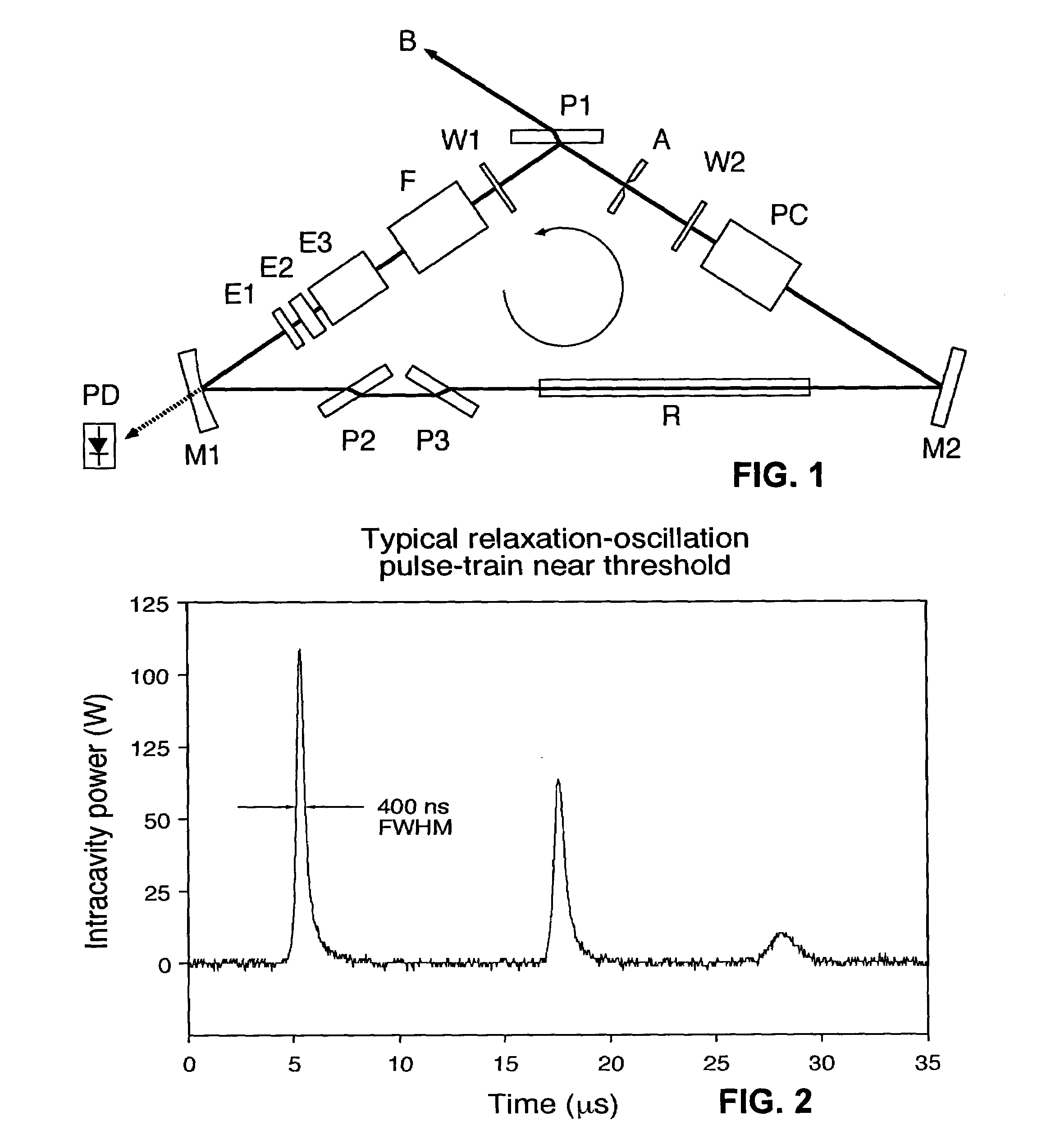
[0037]The basic architecture of the single-frequency Q-switched laser oscillator of an embodiment of the present invention is shown in FIG. 1. Two mirrors M1, M2 and a polarizing beam splitter P1 are arranged to form a resonator in the form of a triangular optical ring. The resonator is housed in a box (not shown) to prevented air turbulence from interfering with operation of the resonator. Going counterclockwise around the ring starting...


PUM

PropertyMeasurementUnit
wavelengthaaaaaaaaaa
radiusaaaaaaaaaa
reflectivityaaaaaaaaaa

Abstract

A method of operating a laser to obtain an output pulse having a single wavelength, comprises inducing an intracavity loss into a laser resonator having an amount that prevents oscillation during a time that energy from the pump source is being stored in the gain medium. Gain is built up in the gain medium with energy from the pump source until formation of a single-frequency relaxation oscillation pulse in the resonator. Upon detection of the onset of the relaxation oscillation pulse, the intracavity loss is reduced, such as by Q-switching, so that the built-up gain stored in the gain medium is output from the resonator in the form of an output pulse at a single frequency. An electronically controllable output coupler is controlled to affect output pulse characteristics. The laser acts a master oscillator in a master oscillator power amplifier configuration. The laser is used for laser peening.

Description

RELATED APPLICATION DATA[0001]The present application claims the benefit of U.S. Provisional Application U.S. Provisional Patent Application No.: 60 / 471,490; entitled SELF-SEEDED SINGLE-FREQUENCY SOLID-STATE RING LASER, AND SINGLE-FREQUENCY LASER PEENING METHOD AND SYSTEM USING SAME, filed 16 May 2003.[0002]The United States Government has rights in this invention pursuant to Contract No. W-7405-ENG-48 between the United States Department of Energy and the University of California for the operation of Lawrence Livermore National Laboratory.BACKGROUND OF THE INVENTION[0003]1. Field of the Invention[0004]The present invention relates to methods using lasers to produce a single-frequency output with a narrow line width, to use of such lasers in master oscillator / power amplifier configurations, and to methods and systems for laser peening based on the same.[0005]2. Description of Related Art[0006]The use of mechanical shocks to form metals and to improve their surface properties has bee...

Claims


Application Information

Patent Timeline
Patent Type & Authority Patents(United States)
IPC IPC(8): H01S3/115H01S3/10B23K26/00B23K103/02C21D10/00H01S3/00H01S3/083H01S3/092H01S3/094H01S3/107H01S3/11H01S3/137H01S3/23
CPCC21D10/005H01S3/083H01S3/2333H01S3/115C21D2221/00H01S3/10038H01S3/10076H01S3/107H01S3/1305H01S3/137H01S3/105H04M1/0214H04M1/0225
Inventor DANE, C. BRENTHACKEL, LLOYDHARRIS, FRITZ B.
Owner METAL IMPROVEMENT CO INC
Why Eureka
Try Eureka