Eureka AIR delivers breakthrough ideas for toughest innovation challenges, trusted by R&D personnel around the world.

Structure of roll blind using dual roller

a technology of double rollers and blinds, applied in the direction of roofs, door/window protective devices, curtain suspension devices, etc., can solve the problems of blinds being unevenly wound, head lining further falling, insufficient interior space of vehicles, etc., and achieve the effect of improving the problem of central deflection

Active Publication Date: 2015-06-11
HYUNDAI MOTOR CO LTD
View PDF4 Cites 6 Cited by
  • Summary
  • Abstract
  • Description
  • Claims
  • Application Information

AI Technical Summary

Benefits of technology

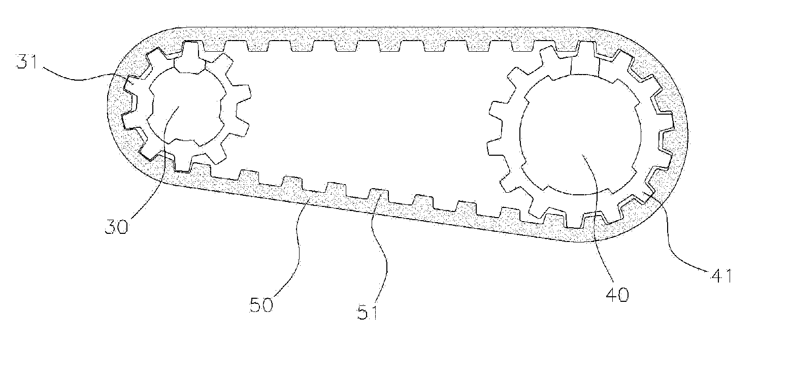
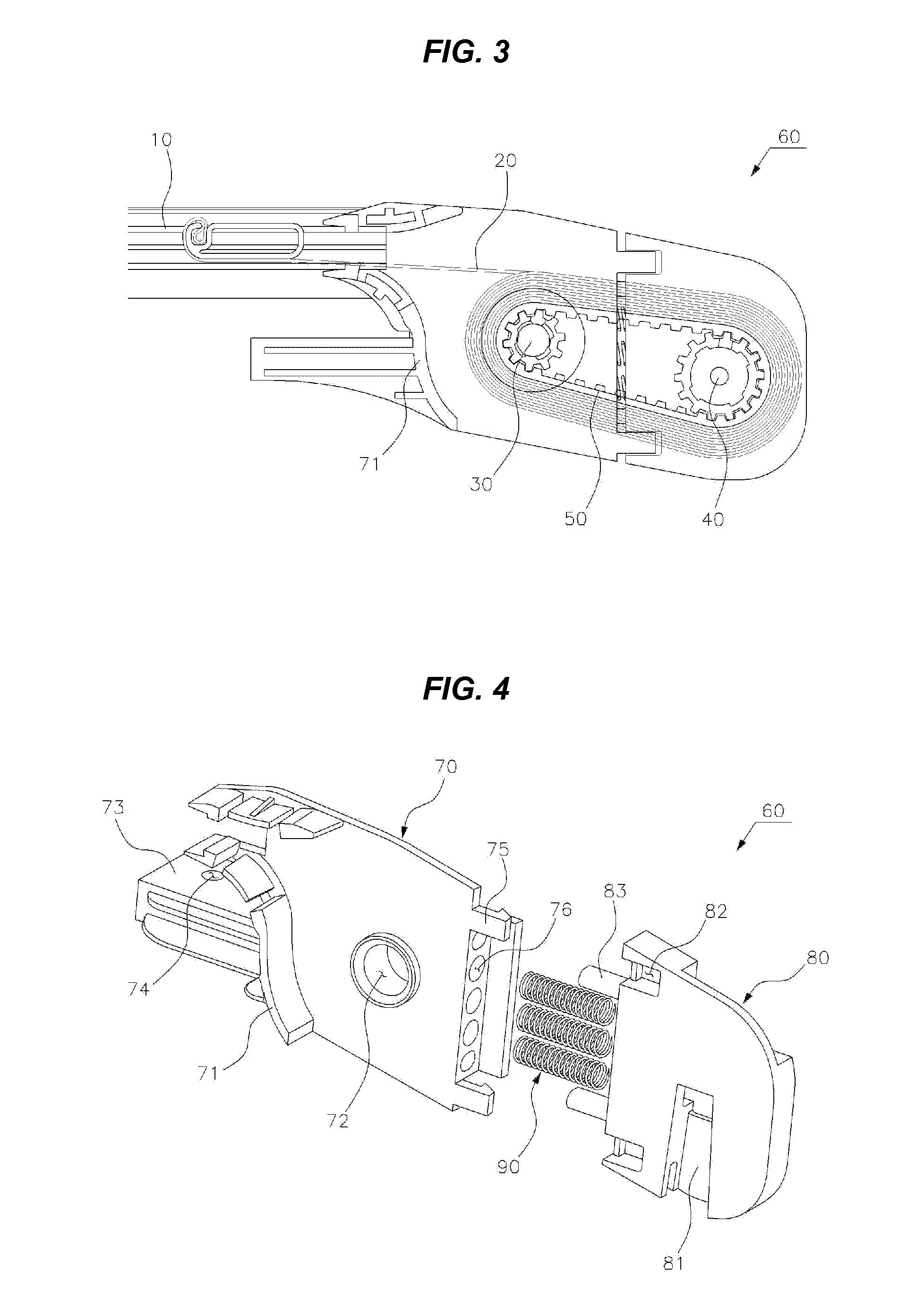
This patent describes a roll blind that uses a double roller to evenly wind the blanket and maintain a constant gap between the main and idle rollers to prevent environmental influences. The serrated and gear portions on the roller and idle roller improve the problem of deflection and slippage between the roller and roller tube. The guide portion ensures constant height of the blanket at the front end of the roller guide, preventing wrinkling. A spring keeps a constant gap between the roller guides and improves the malfunction and slipping problems. A fastening portion makes it easy to replace the main roller and reduces assembly time. The present invention will improve the use and assembly of roll blinds.

Problems solved by technology

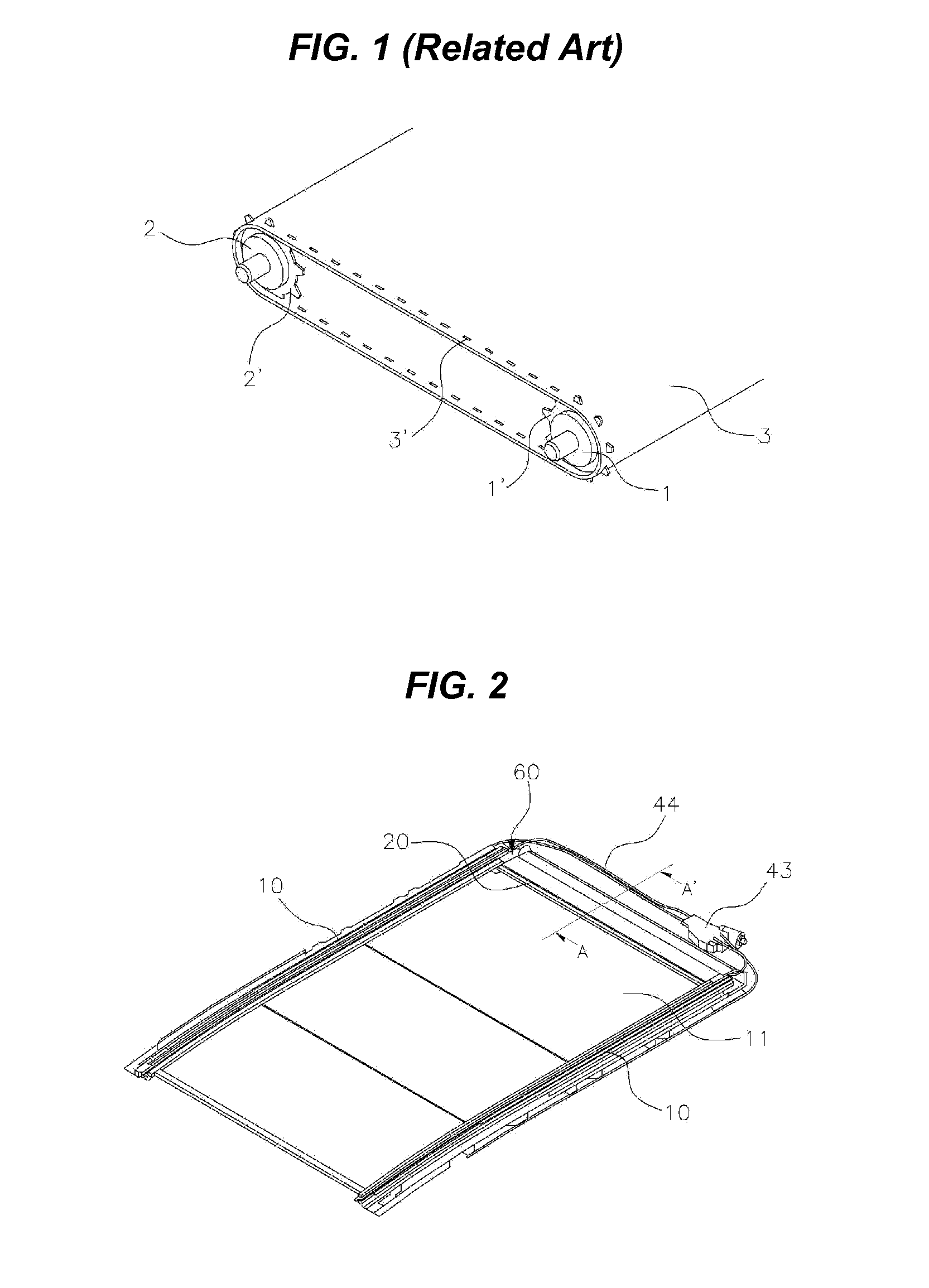
The type of using a sheet of blind is advantageous in that an occupant of a rear seat is able to freely block sunlight when trying to block sunlight by changing a degree of opening of the blind, but since a diameter of the roller around which the blind is wound increases and occupies a wide space compared to the type of using two sheets of blinds, a head lining further comes down, and thus, there is disadvantage in that the interior space of the vehicle become insufficient.
However, in the “conventional double roller type panorama sunroof apparatus”, there were problems in that since there is no guide structure for guiding a movement route of the blind when the blind moves and is wound, the blind is unevenly wound, and thus, wrinkles occur in the blind, and malfunction occurs.
In addition, there is a problem in that when the chain contracts or expands due to the influence of the environment such as a low temperature and high temperature, the blind slips without being tightly wound around the chain, or the main roller and the idle roller are not driven.
Furthermore, there is a problem of deflection of a central part of the chain, by adopting a structure in which the main sprocket and idle sprocket are coupled to both ends of the main roller and the idle roller and the chain hole is coupled thereto, that is, a structure in which only the side portion of the chain is driven.

Method used


Image

  • Structure of roll blind using dual roller
  • Structure of roll blind using dual roller
  • Structure of roll blind using dual roller

Examples


Embodiment Construction

[0045]Reference will now be made in detail to various embodiments of the present invention(s), examples of which are illustrated in the accompanying drawings and described below. While the invention(s) will be described in conjunction with exemplary embodiments, it will be understood that the present description is not intended to limit the invention(s) to those exemplary embodiments. On the contrary, the invention(s) is / are intended to cover not only the exemplary embodiments, but also various alternatives, modifications, equivalents and other embodiments, which may be included within the spirit and scope of the invention as defined by the appended claims.

[0046]A structure of a roll blind using a double roller according to various embodiments of the present invention which includes a blind 20 moving in a front-back direction of a vehicle to selectively shade a sunroof glass 11 disposed in the ceiling portion of a vehicle, may include a pair of sunroof frames 10 formed on both lower...


PUM


Abstract

A structure of a roll blind that moves in a front-back direction of a vehicle to selectively shade a sunroof glass may include a pair of sunroof frames formed on both lower sides of the sunroof glass in a longitudinal direction of the vehicle, a main roller disposed at the one end of the sunroof frame in a vehicle width direction and can rotate through a motor, an idle roller disposed in the vehicle width direction adjacent to the main roller, a roller tube coupled to and wrapping the main roller and the idle roller to form a closed loop, and a roller guide coupled to both ends of the main roller and the idle roller and including a guide portion formed to protrude so that the blind maintains a constant height.

Description

CROSS-REFERENCE TO RELATED APPLICATION[0001]The present application claims priority to Korean Patent Application No. 10-2013-152498 filed Dec. 9, 2013, the entire contents of which is incorporated herein for all purposes by this reference.BACKGROUND OF THE INVENTION[0002]1. Field of the Invention[0003]The present invention relates to a structure of a roll blind that is moved in a front-back direction of a vehicle to selectively shade a sunroof glass, and more particularly, to a structure of a roll blind using a dual roller that includes a main roller that is disposed at one end of a sunroof frame in a vehicle width direction and can rotate through a motor, an idle roller that is disposed in the vehicle width direction adjacent to the main roller, and a roller guide that is coupled to both ends of the main roller and the idle roller, a blind being wound around the main roller and the idle roller.[0004]2. Description of Related Art[0005]On the roof panel of the vehicle, an opening can...

Claims


Application Information

Patent Timeline
IPC IPC(8): E06B9/70B60J3/02E06B9/40
CPCE06B9/70B60J3/0213E06B9/40B60J7/0015E04F10/0607E06B2009/405B60J1/2013B60J7/043B60Y2200/11
Inventor PARK, JAE-HAN
Owner HYUNDAI MOTOR CO LTD
Why Eureka
Eureka Blog
Learn More