
Opening terminal connector

A terminal connector, auxiliary terminal technology, applied in the direction of connection, conductive connection, contact parts, etc., can solve the problems of complex and time-consuming, competitive impact, unfavorable welding operations, etc.

Inactive Publication Date: 2011-07-20
INALWAYS CORPORATION
View PDF0 Cites 0 Cited by
  • Summary
  • Abstract
  • Description
  • Claims
  • Application Information

AI Technical Summary

Problems solved by technology

[0004] However, the operation of fastening the insulating coating material (942) to the fastening hole (922) of the connecting part (921) is complicated and time-consuming, and the shape presented after the fastening is not uniform, which is not conducive to the welding operation Not only does it take quite a long working time to increase the manufacturing cost, but also complicated and subtle operations may lead to a decrease in yield, which will have a negative impact on commercial competitiveness

Method used


Image

  • Opening terminal connector
  • Opening terminal connector
  • Opening terminal connector

Examples


specific Embodiment 1

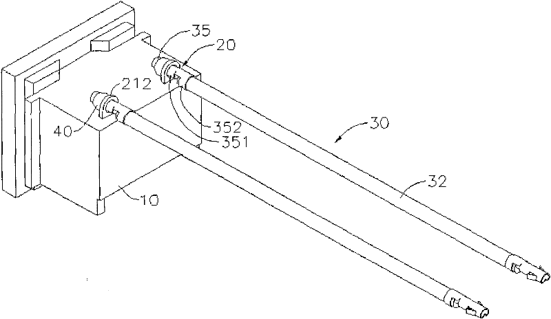
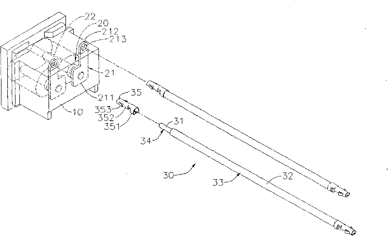
[0025] The open-hole terminal connector includes two auxiliary terminals (20), and each auxiliary terminal (20) has an engaging plate (21) and a conductive plug (22).

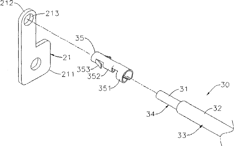
[0026] In the open-hole terminal connector disclosed by the present invention, the engaging plate (21) has a joint portion (211), an engaging portion (212) and an engaging hole (213). The bonding part (211) is bonded to the insulating shell (10), and it is bonded to the insulating shell (10) in a manner of embedding or riveting. When the bonding part ( 211 ) is combined with the insulating casing ( 10 ) by embedding, it can be combined with the embedding mold injection molding method to form a cladding form.

[0027] Such as figure 2 As shown, in the open-hole terminal connector disclosed by the present invention, the engaging portion ( 212 ) is exposed outside the insulating housing ( 10 ). The engaging hole (213) is formed on the engaging part (212). Also, the conductive pin (22) is arranged on the joint ...

specific Embodiment 2

[0030] Such as Figure 4 As shown, another embodiment of the present invention combines the joint portion (211) of the clamping plate (21) with the insulating housing (10) by riveting, and first positions the joint portion (211) on the insulating housing (10) ) outside, and then riveting the joint (211) on the insulating housing (10).

[0031] Because the present invention can conveniently insert and engage the connecting wire (30) on the auxiliary terminal (20) through the above-mentioned structure, and because the engaging portion (353) is formed in a uniform standard, therefore The shape after the engagement is consistent, which is beneficial to a large number of welding operations, and the connection between the connecting wire (30) and the auxiliary terminal (20) can be strengthened by solder (40) smoothly and quickly, thereby reducing the complexity of the operation and greatly Save operating time, improve yield and save manufacturing costs.


PUM


Abstract

The invention relates to an opening terminal connector, comprising an insulating shell, at least one auxiliary terminal and at least one connecting line, wherein each auxiliary terminal is provided with a clamping plate and a conducting plug; the clamping plate is provided with a combined part combined with the insulating shell, a clamping part exposed out of the insulating shell, and a clamping hole formed on the clamping part; the conducting plug is arranged at the combined part of the clamping plate and is fixedly arranged on the insulating shell; each connecting line is provided with a conducting core material, an insulating coating material and a clamping piece; the insulating coating material is coated on the conducting core material; the clamping piece is slightly pipe-shaped, and is provided with a bunching part, a conducting part and a clamping part; the bunching part is bunched on the insulating coating material; the conducting part is connected with the conducting core material; the clamping part is outwards opened from the conducting part towards the bunching part, and is inverted-barb-shaped so as to be clamped in the clamping hole of the auxiliary terminal; and due to the clamping hole for clamping of the auxiliary terminal, the operation complexity is reduced, the operating time is greatly saved, the yield is improved and the manufacturing cost is saved.

Description

technical field [0001] The invention relates to an open-hole terminal connector, in particular to an open-hole terminal connector which achieves a fastening effect by means of a fastening hole and a barb structure. Background technique [0002] see Figure 5 , which expose both terminal connectors. The existing terminal connector includes an insulating shell (91), two auxiliary terminals (92), two conductive plugs (93) and two connecting wires (94). Each auxiliary terminal (92) is respectively riveted on the insulating shell (91) by said one conductive pin (93), and each auxiliary terminal (92) protrudes outwards with a connecting portion (921), at which connecting portion (921) is formed with a series of holes (922). Each connecting wire (94) has a conductive core material (941) and an insulating coating material (942) covering the outer periphery of the conductive core material (941). The end of the conductive core material (941) protrudes from the insulating coating ma...

Claims


Application Information

Patent Timeline
Patent Type & Authority Applications(China)
IPC IPC(8): H01R13/40H01R13/04H01R4/26H01R11/11
Inventor 郑鸿杰林家庆
Owner INALWAYS CORPORATION
Learn More