
Adaptive control of arc welding parameters

A technology of welding parameters and parameters, applied in the direction of arc welding equipment, applications, welding equipment, etc.

Inactive Publication Date: 2011-07-27
J RAY MCCDERMOTT SA
View PDF3 Cites 5 Cited by
  • Summary
  • Abstract
  • Description
  • Claims
  • Application Information

AI Technical Summary

Problems solved by technology

The "line" laser sensor unit projects a laser line within a fixed operating window

Method used


Image

  • Adaptive control of arc welding parameters
  • Adaptive control of arc welding parameters
  • Adaptive control of arc welding parameters

Examples


Embodiment Construction

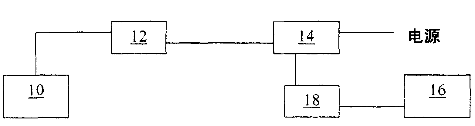
[0016] figure 2 It is a schematic explanatory diagram of the device configuration of the present invention. The equipment configuration includes a laser scanner 10, a laser scanner controller 12, a power adapter 14, a computer 16, and a switch 18 (if necessary). The switch is used to import information into and out of the computer 16.

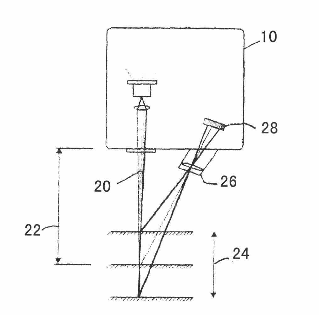
[0017] Such as image 3 As shown, the laser scanner 10 projects a laser line 20 in a fixed operating window including a reference distance 22 and a measurement range 24. The laser generates a reflection position of anything that the laser line 20 "sees" in the operating window. The lens 26 focuses the laser reflection on the CCD 28. For use in the welding operation, the reflected signal received by the CCD 28 is recorded by the computer 16. With the help of triangulation, the precise distance of the object from the laser can be measured at any point along the laser line. The recorded laser reflection measurements provide a 360 degree actual jo...


PUM


Abstract

The present invention discloses an adaptive control of arc welding parameters, which comprises a laser sensor to scan the weld joint either before welding begins as a pre-weld scanning operation or in real time during welding to provide adaptive control of the arc welding parameters. A "line" type laser sensor device projects a laser line within a fixed operating window. The line laser produces a reflective position of anything that the laser line "sees" within the operating window. By triangulation, the exact distance an object is from the laser can be measured at any point along the "line" of the laser. Certain parts of the weld bevel are targeted for measurement. The measurements are stored in an electronic storage medium and a data processor. The stored measurements and data processor are used in conjunction with automated welding equipment to adjust the welding parameters as required. Because the exact joint / weld geometry is then known for every portion of the weld, the welding equipment can then respond or "adapt" to variations in the weld joint between the work pieces.

Description

Technical field [0001] The present invention relates generally to welding operations, and more specifically to adaptive control of arc welding parameters. Background technique [0002] Narrow groove welding is widely used in pipeline construction in the world. Although many automated systems use multiple control systems and methods, the precise geometry of the welded joint is unknown when welding. The reason why the precise welded joint geometry is unknown is that the welded joint is composed of many elements that individually or collectively produce errors for the desired joint design. Among the contributing factors are: [0003] *Pipe end beveling machine, which introduces tolerances such as the following for joint preparation variables: 1) bevel angle, 2) bevel obtuse edge, 3) bevel angle "set-out" or "offset" (see figure 1 ). [0004] *The dimensional tolerance of pipeline pipe used in any given pipeline project. The dimensional tolerance varies with different projects, and i...

Claims


Application Information

Patent Timeline
Patent Type & Authority Applications(China)
IPC IPC(8): B23K9/095
CPCB23K9/1274B23K9/0956B23K9/0286B23K37/0276B23K2101/10
Inventor T·E·多伊尔T·L·布莱奥克斯C·D·诺埃尔T·N·耶叟
Owner J RAY MCCDERMOTT SA
Learn More