Relay

A relay and base technology, applied in the field of electronic control devices, can solve the problems of collision, glue easy to lose viscosity, easy to fall off, etc., and achieve the effect of high work sensitivity

Active Publication Date: 2011-07-27
NINGBO TIANBO GANGLIAN ELECTRONICS
View PDF5 Cites 4 Cited by
  • Summary
  • Abstract
  • Description
  • Claims
  • Application Information

AI Technical Summary

Problems solved by technology

[0003] 1) Since the yoke is bonded to the base by glue, the glue will easily lose its viscosity due to temperature changes, use time and other external factors, or it will easily fall off due to external force. detached from the base, so that the relay will not work properly
[0004] 2) Since the glue is bonded, there is no accurate positioning and assembly, so the installation position of the yoke will deviate, so that the magnetic field generated by the relay during operation will be affected, further affecting the working performance of the relay
[0005] 3) Since the armature is riveted on the yoke, the matching force of the armature to the yoke cannot be accurately controlled after riveting. In other words, the relative position of the armature and the yoke cannot be controlled very accurately during riveting. Therefore, the end of the armature and the push plate will lean forward or backward: for the armature to lean forward, it will cause the push plate to also lean forward, so that the stroke of the push plate will be shortened, resulting in The contact of the moving reed is relatively close to the contact of the static reed, so that the work of the relay is insensitive; for the backward tilt of the armature, the push plate and the armature will be loosened, which will cause collision and produce abnormal noise, and It will also affect the working sensitivity of the relay

Method used


Image

  • Relay
  • Relay
  • Relay

Examples


Embodiment Construction

[0026] The present invention will be described in further detail below in conjunction with the accompanying drawings and specific embodiments.

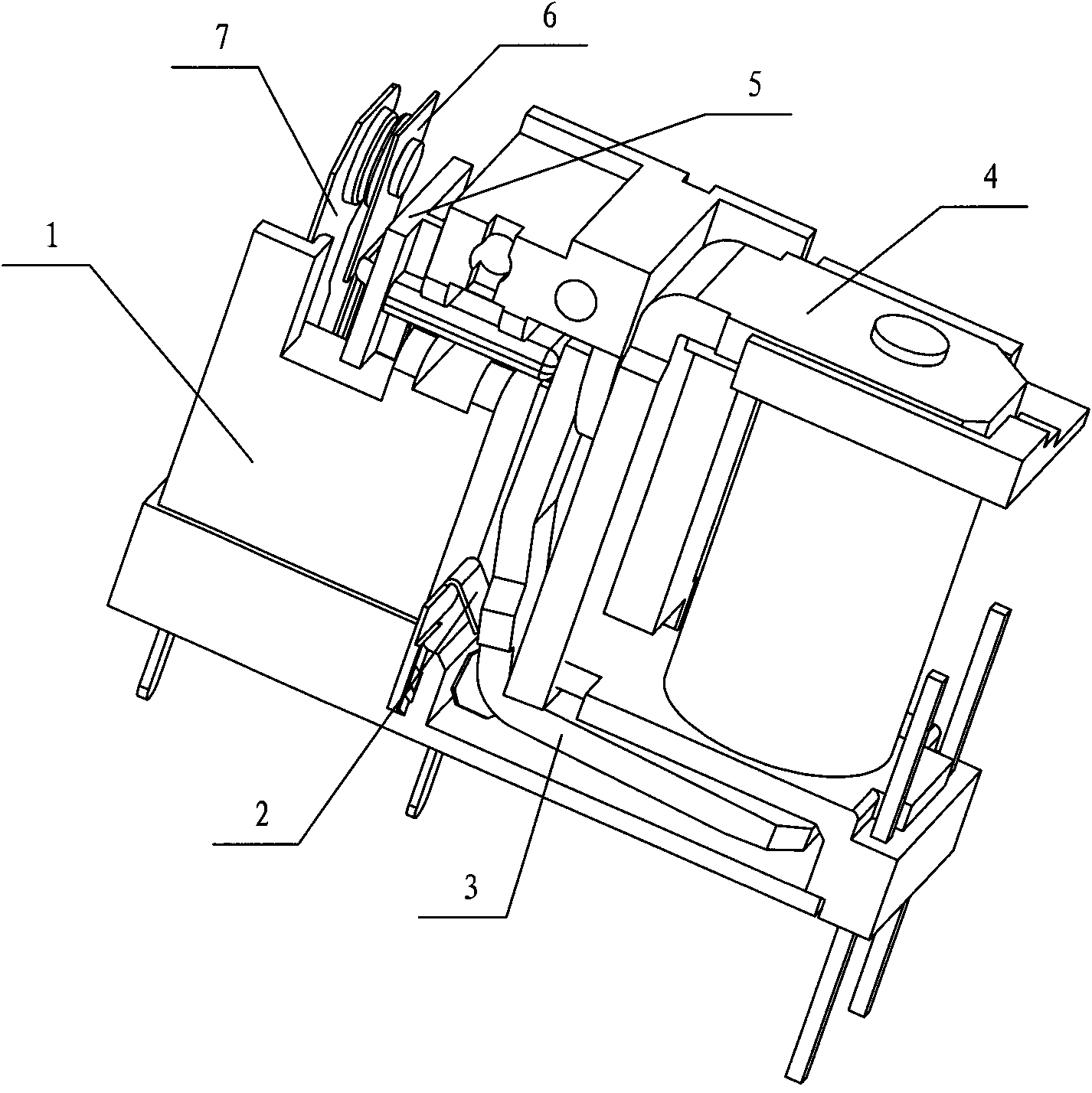
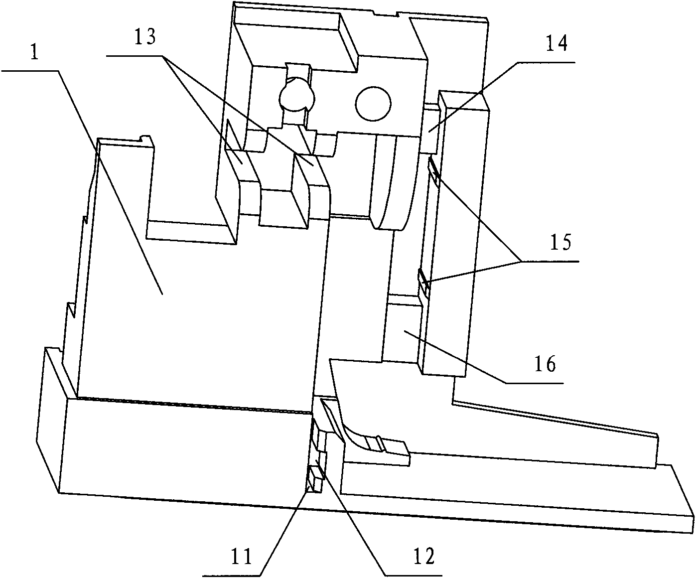
[0027] Depend on Figure 1 to Figure 9 The shown schematic diagram of the structure of the relay of the present invention shows that it includes a base 1, a yoke 4, an armature 3, a shrapnel 2, a push plate 5, a moving reed 6 and a static reed 7, and the yoke 4, the armature 3 , push plate 2, moving reed 6 and static reed 7 are all installed on the base 1, the yoke 4 is inverted L-shaped, one end of the yoke 4 is connected with the base 1, and the armature 3 is also It is L-shaped, the elastic piece 2 is clamped on the base 1, and the bending part of the armature 3 is pressed against the other end of the yoke 4; the base 1 has a positioning structure, and the yoke The iron 4 is installed on the base 1 through a positioning structure.

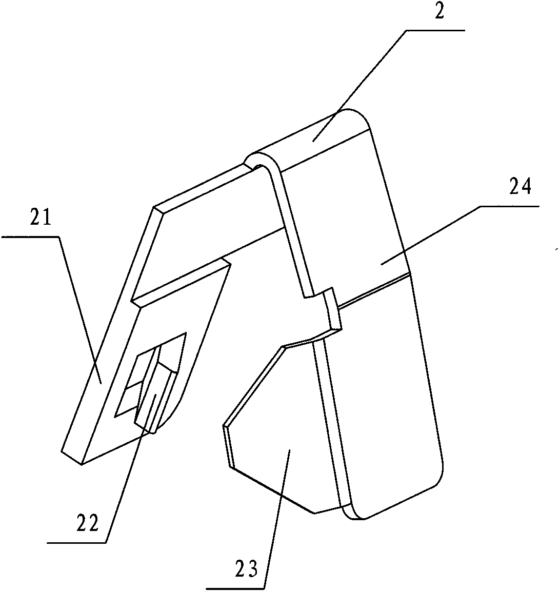
[0028] The elastic piece 2 is an inverted V shape with a left hypotenuse 21 and a right hypotenuse...


PUM


Abstract

The invention discloses a relay, which comprises a pedestal (1), a yoke (4), an armature (3), an elastic sheet (2), a push plate (5), a movable reed (6), and a static reed (7), wherein the yoke (4), the armature (3), the push plate (5), the movable reed (6), and the static reed (7) are all mounted on the pedestal (1); the yoke (4) is of a reversed L shape; one end of the yoke (4) is connected with the pedestal (1); the armature (3) is also of an L shape; the elastic sheet (2) is blocked on the pedestal (1); and the bending part of the armature (3) is tightened against the other end of the yoke (4); a locating structure is arranged on the pedestal (1); and the yoke (4) is arranged on the pedestal (1) through the locating structure. After the structure is adopted, the phenomenon that the yoke is separated from the pedestal is avoided; therefore, the normal working of the relay is guaranteed; meanwhile, the elastic sheet only applies a force on the bending part of the armature; and the acting force of the armature on the push plate is automatically adjusted, therefore, the relay is guaranteed to have very high working sensitivity.

Description

technical field [0001] The invention relates to an electronic control device, specifically a relay. Background technique [0002] Relay is an electronic control device, which is usually used in automatic control circuit, and plays the role of automatic adjustment, safety protection, conversion circuit, etc. in the circuit. Relays generally include moving and static reeds, bases, yokes, coils, armatures, shrapnel and other components, among which, moving and static reeds, yokes, armatures, coils, shrapnel and other components are all installed on the base. In the relays in the prior art, the yoke is usually glued to the corresponding position of the base, and the armature is riveted on the yoke. Therefore, this structure has the following disadvantages: [0003] 1) Since the yoke is bonded to the base by glue, the glue will easily lose its viscosity due to temperature changes, use time and other external factors, or it will easily fall off due to external force. detached f...

Claims


Application Information

Patent Timeline
Patent Type & Authority Applications(China)
IPC IPC(8): H01H50/16
Inventor 王尚武王铁伟王坚敏
Owner NINGBO TIANBO GANGLIAN ELECTRONICS
Why Eureka
Try Eureka