
Crimping radio frequency coaxial connector

A radio frequency coaxial connector technology, applied in the direction of connection, two-part connection device, connection with permanent deformation, etc., can solve thread slippage, affect the crimping firmness of radio frequency coaxial connector and transmission cable, reduce Problems such as the fastening force of the connecting sleeve and the connecting inner sleeve, etc., achieve the effect of convenient use

Inactive Publication Date: 2011-07-27
镇江市胜超电子有限公司
View PDF4 Cites 7 Cited by
  • Summary
  • Abstract
  • Description
  • Claims
  • Application Information

AI Technical Summary

Problems solved by technology

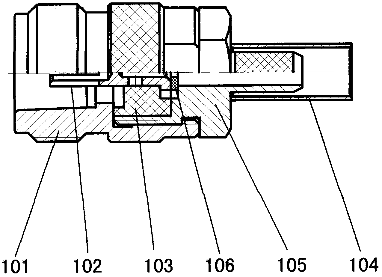
[0004] This prior art crimping type radio frequency coaxial connector not only has as many as 6 parts, but also has as many as 12 operations for crimping the end of the transmission cable during use; moreover, the connection that produces the fastening force For the 7-8 threads between the sleeve and the connecting inner sleeve, due to the need to open an assembly window during the assembly process, a quarter of the outer circumference of the connecting inner sleeve and the threads on it have to be cut off, which greatly reduces the The fastening force between the connecting sleeve and the connecting inner sleeve directly affects the crimping firmness between the RF coaxial connector and the transmission cable, making it unable to withstand the pull of a large external force. In addition, sometimes the thread will Slip teeth, so it often happens that it falls off during use

Method used


Image

  • Crimping radio frequency coaxial connector
  • Crimping radio frequency coaxial connector
  • Crimping radio frequency coaxial connector

Examples


Embodiment Construction

[0016] Implementation details of the present invention are described as follows in conjunction with accompanying drawing:

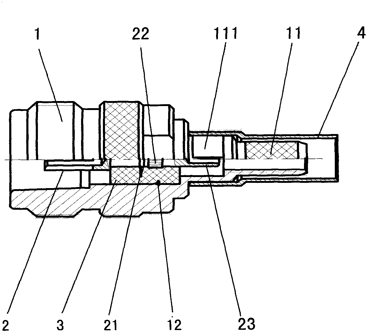
[0017] like figure 1 , 7 As shown in , 8, a crimping type radio frequency coaxial connector, including the connecting sleeve 1 provided with connecting threads and ring-shaped reticulated protrusions on the shell of the connecting end, the plug-in end and the welding end are all in the shape of tube holes. The conductor 2 is sleeved outside the inner conductor and the insulating sleeve 3 embedded in the inner cavity of the connecting sleeve, and the crimping sleeve 4 for crimping the cable is characterized by

[0018] ——The crimping end of the connecting sleeve is designed to be integrated with the connecting sleeve body, and has a stepped tubular crimping head 11 with a larger neck outer diameter and a smaller head outer diameter;

[0019] - The neck of the tubular crimping joint of the connecting sleeve is designed with a welding operation window 111...


PUM


Abstract

The invention discloses a crimping radio frequency coaxial connector, belonging to the radio frequency coaxial connectors. Aiming at the problems that the similar connector is complex in operation and sometime falls off when in use, the adopted technical scheme is as follows: the crimping end of a connecting sleeve is designed into a tubular crimping head with a larger external diameter of the neck and a smaller external diameter of the head, wherein the tubular crimping head is provided with steps and integrated with the connecting sleeve body into a whole; a welding operation window is designed at the neck of the tubular crimping head of the connecting sleeve; a ring-shaped bulge the cross section of which is in a wedge tooth shape is designed on a scarf joint insulation sleeve of the cavity in the connecting sleeve; a ring-shaped bulge the cross section of which is in a wedge tooth shape is designed on the scarf joint insulation sleeve on the periphery of an inner conductor; a ring-shaped bulge the surface of which is provided with axial horizontal streaks is arranged on the scarf joint insulation sleeve of the periphery of the inner conductor; and the tubular welding end of the inner conductor is designed into a semi-tubular inclined opening. After the coaxial connector is on trial, we can find that the number of the components is reduced to 4 from 6; the crimping working procedures are reduced to 5 from 12; the falling-off condition does not occur in using; the electric property is improved; and the voltage standing wave ratio is reduced to 1.15 / 3GHz from 1.25 / 3GHz.

Description

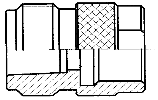
technical field [0001] The invention relates to a radio frequency coaxial connector, in particular to a crimping type radio frequency coaxial connector which is crimped at the end of a transmission cable. Background technique [0002] The structure of the existing crimping type RF coaxial connector for similar purposes is as follows: Figure 2-6 shown, including: image 3 The shown connecting end housing is provided with a connecting thread and a tubular connecting sleeve 101 protruding from the annular pattern, such as Figure 5 The shown plug-in end and welding end are all tube hole-shaped inner conductors 102, such as Image 6 As shown, the insulating sleeve 103 that is sleeved outside the inner conductor and embedded in the inner cavity of the connecting sleeve, and the crimping sleeve 104 for crimping the cable, as well as Figure 4 As shown, one end is provided with a tubular crimping joint, and the outer periphery of the other end is provided with a connecting inner...

Claims


Application Information

Patent Timeline
IPC IPC(8): H01R13/02H01R13/46H01R24/40H01R4/20
Inventor 王利君朱宝华
Owner 镇江市胜超电子有限公司
Learn More