
Elevator device

A technology for elevators and motors, which is used in elevators, transportation and packaging in buildings, and can solve problems such as poor environmental load, larger volume, and larger equipment.

Inactive Publication Date: 2011-08-03
TOSHIBA ELEVATOR KK
View PDF5 Cites 3 Cited by
  • Summary
  • Abstract
  • Description
  • Claims
  • Application Information

AI Technical Summary

Problems solved by technology

[0005] In the above-mentioned conventional elevator apparatus, since oil is used, it is not good from the viewpoint of environmental load.
In addition, since oil with a small specific gravity is used, there is a problem that the volume of the tank itself increases and the size of the equipment also increases.

Method used


Image

  • Elevator device
  • Elevator device
  • Elevator device

Examples


Embodiment Construction

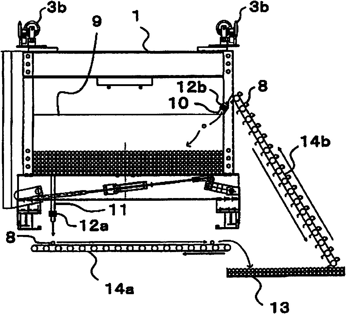
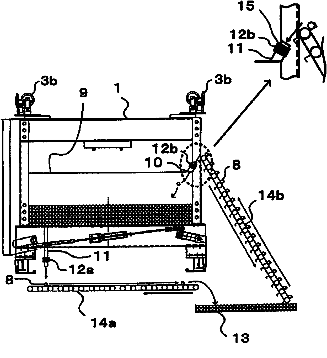
[0049] Hereinafter, embodiments of the elevator apparatus of the present invention will be described in detail with reference to the drawings. In addition, the Example described below is just an Example of this invention, and of course this invention is not limited to these.

[0050] The elevator device of the present embodiment is composed of a bucket type elevator device and an automatic weight adjustment device.

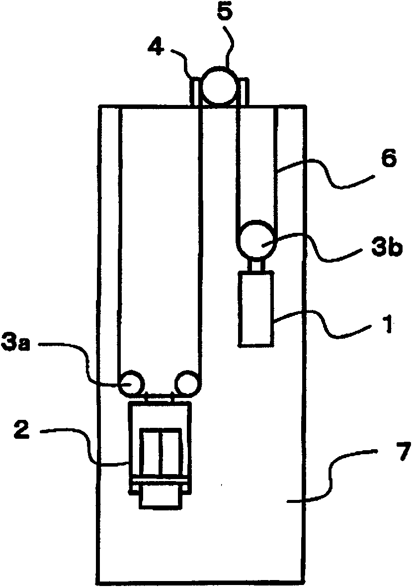
[0051] like figure 1 As shown, the bucket elevator device of the present embodiment consists of a counterweight 1, a car 2, and suspension wheels 3a, 3b respectively installed on the top of the counterweight 1 and the car 2, and a driving sheave 5 equipped in the hoisting machine 4. , main rope 6 and hoistway 7 constitute. One end of the main rope 6 is fixed on the top of the hoistway 7, and is drawn around in the order of the hanging sheave 3a of the car 2, the driving sheave 5, and the hanging sheave 3b of the counterweight 1, and the other end is fixed on th...


PUM


Abstract

An elevator device allows an automatic adjustment of counterweight mass or elevator car mass in an equipped elevator. The elevator device of the invention is characterized in that the device comprises a rope for connecting an elevator car with a counterweight; a sheave for winding and hanging the rope; a motor for driving the sheave; a receiving case for heavy object disposal, which is disposed on the counterweight or the elevator car and has an open-closed insert opening and discharge opening for hard spheres; a storing field for storing the hard spheres; a first transporting part for transporting the hard spheres discharged from the discharge opening to the storing field; a second transporting part for transporting the hard spheres from the storing field to the insert opening; a first counter for counting the number of the hard spheres dicharged from the discharging opening; and a second counter for counting the number of the hard spheres inserted into the insert opening.

Description

technical field [0001] The present invention relates to an elevator installation capable of automatically adjusting the counterweight or the mass of the car. Background technique [0002] Figure 13 It is a schematic system diagram showing the relationship between the counterweight and the car of the conventional elevator apparatus. That is, the counterweight 101 and the car 102 are connected by the main rope 103, etc., and the main sheave 105 is rotated by the hoist 104, and the main rope 103 is moved up and down to lift the counterweight 101 or the car 102. The main rope 103 wound around the hoist 104 is stretched toward both the counterweight 101 side and the car 102 side. In general, the mass of the counterweight 101 after the installation of the elevator device is constant, but the mass of the car 102 varies depending on the number and weight of passengers and cargo. Therefore, the load on the hoist 104 that moves the main rope 103 to the heavier side of the counterwe...

Claims


Application Information

Patent Timeline
Patent Type & Authority Applications(China)
IPC IPC(8): B66B11/00B66B11/02
Inventor 浦田尚纪
Owner TOSHIBA ELEVATOR KK
Learn More