Solar heat collection automatic gradient phase change heat storage energy gradient utilization device

A technology of solar heat collection and phase change heat storage, which is applied in the field of solar energy utilization and phase change heat storage, can solve problems such as overheating of phase change materials, excessive solar heat energy, automatic adjustment of phase change material quality and heat storage temperature, etc., to achieve Improve the utilization rate and ensure the effect of heat storage

Inactive Publication Date: 2016-05-11
NORTH CHINA UNIVERSITY OF TECHNOLOGY
View PDF5 Cites 12 Cited by
  • Summary
  • Abstract
  • Description
  • Claims
  • Application Information

AI Technical Summary

Problems solved by technology

But in the existing solar phase change material heating technology, the phase change temperature and heat storage capacity of the phase change material are all fixed, and such technology has the following disadvantages: (1) in the weather with strong solar radiation, the solar thermal energy supplied to the phase change material If it is too large, the phase change material will be overheated, which will affect the service life of the phase change material
(2) In the weather with weak solar radiation, the solar heat energy supplied to the phase change material is too little, the phase change material cannot be completely phase changed, and the energy storage potential of the phase change material is not fully utilized
(3) The solar heat collector and the phase change heat storage device are set separately, and the middle is connected by pipes, etc., so that the system efficiency is reduced due to the heat dissipation of the pipes and the addition of a heat exchange link
In the prior art, there is no technology that can automatically adjust the quality and heat storage temperature of phase change materials involved in heat storage according to solar radiation

Method used


Image

  • Solar heat collection automatic gradient phase change heat storage energy gradient utilization device
  • Solar heat collection automatic gradient phase change heat storage energy gradient utilization device
  • Solar heat collection automatic gradient phase change heat storage energy gradient utilization device

Examples


Embodiment 1

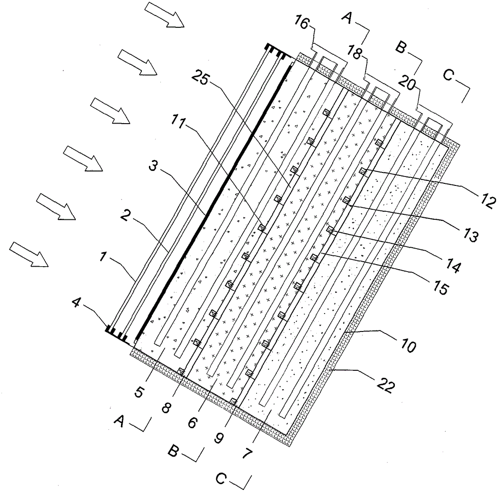
[0033] as attached figure 1 As shown, the solar heat collection automatic cascade phase change heat storage energy cascade utilization device includes: outer glass 1, inner glass 2, selective absorption film 3, fixed bracket 4, high temperature phase change heat storage layer 5, automatic Heat conduction layer 8, medium temperature phase change heat storage layer 6, automatic heat conduction layer 9, low temperature phase change heat storage layer 7, high temperature adsorption chamber 11, low temperature adsorption chamber 12, baffle plate 13, ventilation net 14, steam chamber 15, steam chamber 25 , water inlet pipe 16, water outlet pipe 17, water inlet pipe 18, water outlet pipe 19, water inlet pipe 20, water outlet pipe 21, housing 10, insulation layer 22, and the automatic heat conduction layer 8 is located at the high temperature phase change heat storage layer 5 and the medium temperature phase Between the variable heat storage layers 6, the automatic heat conduction lay...

Embodiment 2

[0036] The main difference between Example 2 and Example 1 lies in the arrangement of the phase-change heat storage layer and its automatic heat-conducting layer adsorption chamber. In Example 2, the integrated phase-change heat storage layer in Example 1 is replaced by a combined phase-change heat storage layer. heat storage layer, and the low thermal conductivity baffle plate 13 is cancelled, and other structural settings are the same. like Figure 5 As shown, in the weather with strong solar radiation, after the selective absorption film 3 absorbs sunlight, the temperature rises to directly heat the high-temperature phase-change thermal storage layer 5, and the high-temperature phase-change thermal storage layer 5 in the high-temperature phase-change thermal storage layer 5 The temperature change material gradually heats up and undergoes a phase change. After the high temperature phase change material reaches the phase change temperature, the high temperature adsorbent in t...

Embodiment 3

[0038] The main difference between embodiment 3 and embodiment 1 lies in the automatic adjustment method of the automatic heat conduction layer. In embodiment 3, the expansion ribs 23 are used to replace the adsorption chamber 11, adsorption chamber 12, baffle plate 13, air mesh 14, The steam chamber 15 and the steam chamber 25 have the same configuration as other structures. as attached Figure 7 As shown, the fins located in the automatic heat-conducting layer 8 are embedded in the high-temperature phase-change heat storage layer 5, and are at a certain distance from the medium-temperature phase-change heat storage layer 6 at low temperature; the expansion fins located in the automatic heat-conducting layer 9 are embedded in the medium-temperature In the phase change heat storage layer 6, there is a certain distance from the low temperature phase change heat storage layer 7 at low temperature. In the weather with strong solar radiation, after the selective absorption film 3...


PUM


Abstract

The invention proposes a solar heat collection automatic gradient phase change heat storage energy gradient utilization device. The device comprises such parts as a solar heat collecting layer, a gradient phase change heat storage layer, an automatic heat conducting layer and a shell. The solar heat collecting layer is arranged on the outer side of a high-temperature phase change heat storage layer; the gradient phase change heat storage layer includes the high-temperature phase change heat storage layer, a medium-temperature phase change heat storage layer and a low-temperature phase change heat storage layer; and the automatic heat conducting layer is arranged among the phase change heat storage layers for automatically building/cutting a transfer heat bridge among the phase change heat storage layers. The solar heat collection automatic gradient phase change heat storage energy gradient utilization device can adapt to solar radiation change to automatically adjust the quality of a phase change material participating in heat storage, to guarantee the phase change material to fully generate the phase change and to fully exert the phase change potential of the phase change material, and can realize gradient utilization of solar heat energy to achieve the purpose of improving the solar utilization rate.

Description

technical field [0001] The invention relates to the technical field of solar energy utilization and phase change heat storage, and more specifically relates to a solar energy automatic cascade phase change heat storage energy cascade utilization device. Background technique [0002] Due to the instability and intermittent nature of solar energy, it has brought great difficulties to the utilization of solar energy. Phase change materials have the characteristics of large heat storage and heat storage and release at approximately constant temperature, which can well balance the imbalance between solar energy supply and heat energy demand, and have great application potential. But in the existing solar phase change material heating technology, the phase change temperature and heat storage capacity of the phase change material are all fixed, and such technology has the following disadvantages: (1) in the weather with strong solar radiation, the solar thermal energy supplied to t...

Claims


Application Information

Patent Timeline
Patent Type & Authority Applications(China)
IPC IPC(8): F24J2/34F24J2/48
CPCF24S60/00F24S70/10F24S60/10Y02B10/20Y02E10/40
Inventor 李志永李文丰付学友
Owner NORTH CHINA UNIVERSITY OF TECHNOLOGY
Why Eureka
Try Eureka