A plunger-free dual-channel output pump system

A dual-channel, output pump technology, used in lubrication pumps, engine components, engine lubrication, etc., can solve problems such as high pumping speed, fast plunger movement, and damage to the grease soap structure, and achieves pumping resistance and Effects of reduced pressure, reliable power transmission, and reduced processing costs

Active Publication Date: 2014-10-01
SHANGHAI F&S BEARING TECH
View PDF4 Cites 0 Cited by
  • Summary
  • Abstract
  • Description
  • Claims
  • Application Information

AI Technical Summary

Problems solved by technology

[0004] 1. Due to the relatively long mating surface of the plunger and the plunger hole and the relatively fast movement speed of the plunger, there is no sealing ring installed on the plunger, and the matching gap between the plunger and the plunger hole is required to be very small, which inevitably requires the plunger and the plunger hole. The plunger hole has extremely high machining accuracy, which means high manufacturing cost;
[0005] 2. A pump system can only output one lubrication point. For a lubrication system, if you want to lubricate multiple lubrication points, you must arrange multiple pump systems or use a distributor, and the distributor is also a multi-channel precision plunger structure. Manufacturing costs are also higher;
[0006] 3. Due to the special plunger structure of the current pump system and distributor, it is inevitable that there will be problems of excessive pumping speed and high pressure when the lubricant is delivered to the lubrication point. When pumping grease, there will be damage The hidden danger of the grease soap structure, when the grease viscosity is high, the consistency is large (such as grease No. 2 and above), and the temperature is low, the possibility of damage to the grease soap structure is significantly increased. Therefore, Existing pump systems and dispensers are often referred to as "grease killers";
[0007] 4. The shape of the current pump system is irregular and long, which occupies a large space in the length direction, resulting in an increase in the volume of the lubrication system and an increase in manufacturing costs

Method used


Image

  • A plunger-free dual-channel output pump system
  • A plunger-free dual-channel output pump system
  • A plunger-free dual-channel output pump system

Examples


Embodiment Construction

[0035] Please refer to the accompanying drawings to describe a specific embodiment of the present invention.

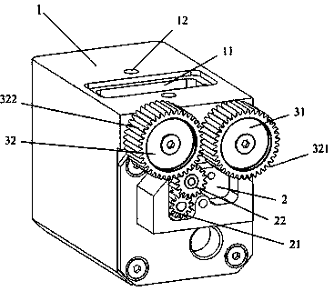
[0036]Plunger-less dual-channel output pump system, including: pump body 1, drive motor 2 and lubricant pumping transmission unit, the shell of the pump system is a cube, which can be a semi-hollow structure, and the drive motor 2 is located in the pump body 1 In the lower part, a lubricant storage unit 11 is arranged above the pump body 1 , and a first pumping channel 31 and a second pumping channel 32 are arranged in parallel in the pump body 1 . The first lubricant pumping transmission unit and the second lubricant pumping transmission unit are respectively located in the first pumping channel 31 and the second pumping channel 32 .

[0037] The first pumping channel 31 and the second pumping channel 32 communicate with the lubricant storage unit 11 respectively, and the driving motor 2 is provided with a driving wheel 21 and a driven wheel 22, and the driving wheel...


PUM


Abstract

The invention relates to a plunger-free two-channel output pump system comprising a pump body, a drive motor and two lubricant pumping transmission units, wherein the drive motor is arranged at the lower part of the pump body; the two lubricant pumping transmission units are respectively arranged in two pumping channels at the upper part of the pump body; the top of the pump body is provided with a lubricant storage unit and a lubricant fixing device screw hole; one lubricant pumping transmission unit is driven by a drive unit to carry out a process of sucking the lubricant and the other lubricant pumping transmission unit is driven to carry out a process of pumping the lubricant in the mean time; the two lubricant pumping transmission units are circularly and alternately operated respectively between the processes of sucking and pumping the lubricant; and the lubricant which is pumped from the lubricant storage unit to the pumping channels is output from the pumping channels. In the pump system provided by the invention, a plunger-free structure is adopted and the power is transmitted through gear engagement and thread engagement; and therefore, very high machining precision is not needed in the pump system provided by the invention, number 3 lubricating grease can be pumped and can be pumped at a low temperature without being heated.

Description

technical field [0001] The invention relates to the technical field of industrial lubricators or lubricating systems, in particular to a plunger-free dual-channel output pump system for the lubricating system. Background technique [0002] During the operation of mechanical equipment, bearings, gears, ball screws and other moving friction pairs need to be replenished with lubricant during their life cycle. The replenishment methods can be divided into manual filling and automatic lubrication system filling. At present, all lubricating systems include a core component—a pump system. Figure 1 is a pump system generally used in an existing lubricating system, which mainly includes: a pump body 51, a transmission plunger 54, a control plunger 53 and a spring 52, wherein Figure 1A for the lubricant sucking state, Figure 1B Lubricant pumping status. Such as Figure 1A , one end of the transmission plunger 54 (the right end in the figure) is connected to the rotating eccentric m...

Claims


Application Information

Patent Timeline
Patent Type & Authority Patents(China)
IPC IPC(8): F16N13/02F16N13/10
Inventor 赵联春陈淑英
Owner SHANGHAI F&S BEARING TECH
Why Eureka
Try Eureka