Double-evaporation-temperature air conditioner with temperature and humidity controlled independently

An independently controlled, high-temperature evaporator technology, applied in heating and ventilation control systems, irreversible cycle compressors, refrigerators, etc., can solve the problem of high-temperature evaporator side cooling capacity limitation, independent control of temperature and humidity, and large differences in evaporation temperature Large and other problems, to achieve the effect of convenient operation, simple equipment, and improved efficiency

Inactive Publication Date: 2011-08-03
TSINGHUA UNIV
View PDF9 Cites 15 Cited by
  • Summary
  • Abstract
  • Description
  • Claims
  • Application Information

AI Technical Summary

Problems solved by technology

The two-stage evaporating temperature difference of the refrigeration cycle disclosed in Chinese Document 2 is relatively large (about 30°C), and it is suitable for a dual-temperature refrigerator with refrigeration and freezing functions. Part or all of the liquid refrigerant flowing out of the condenser enters the ejector for induction. The refrigerant evaporated on the high-temperature evaporator side, due to the limited injection capacity of the ejector, the cooling capacity of the high-temperature evaporator side is correspondingly limited
For air-conditioning systems that independently control temperature and humidity using condensation dehumidification, the difference in the two-stage evaporating temperature requirements is not too large (generally within 15°C), and the required high-temperature evaporator side cooling capacity is much greater than the low-temperature evaporator side cooling capacity , the dual-temperature compression / jet refrigeration cycles mentioned in this document cannot be directly used in air-conditioning systems with independent control of temperature and humidity

Method used


Image

  • Double-evaporation-temperature air conditioner with temperature and humidity controlled independently
  • Double-evaporation-temperature air conditioner with temperature and humidity controlled independently
  • Double-evaporation-temperature air conditioner with temperature and humidity controlled independently

Examples


Embodiment Construction

[0016] The present invention will be described in detail below in conjunction with the accompanying drawings and embodiments.

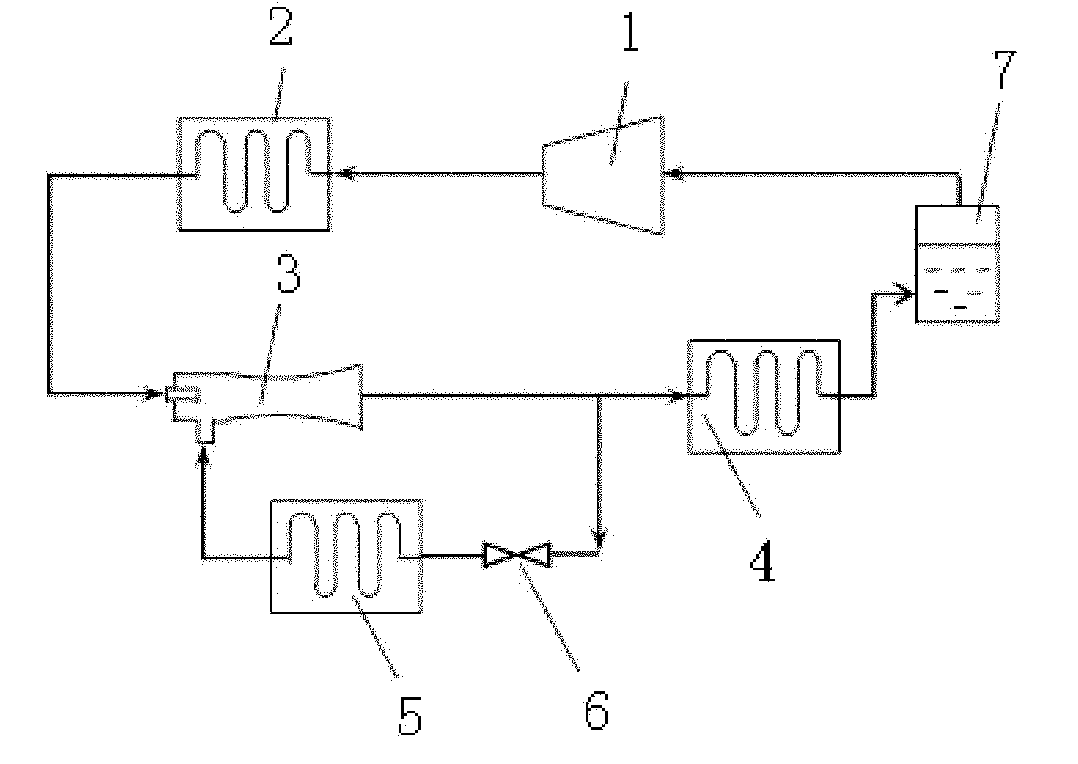
[0017] Such as figure 1 As shown, the present invention includes a compressor 1 , a condenser 2 , an ejector 3 , a high-temperature evaporator 4 , a low-temperature evaporator 5 , a throttling device 6 and a gas-liquid separator 7 . Wherein, the outlet of the compressor 1 is connected to the inlet of the condenser 2 . The first inlet of the ejector 3 is connected with the outlet of the condenser 2 , and the second inlet is connected with the outlet of the low temperature evaporator 5 . The outlet of the ejector 3 is divided into two routes, one route is connected to the inlet of the low-temperature evaporator 5 through the throttling device 6, the other route is connected to the inlet of the high-temperature evaporator 4, and the outlet of the high-temperature evaporator 5 is connected to the compressed air through the gas-liquid separator 7 Import...


PUM


Abstract

The invention relates to a double-evaporation-temperature air conditioner with temperature and humidity controlled independently, which is characterized by comprising a compressor, a condenser, an ejector, a high-temperature evaporator, a low-temperature evaporator, a throttling device and a gas-liquid separator, wherein an outlet of the compressor is connected with an inlet of the condenser; a first inlet of the ejector is connected with an outlet of the condenser and a second inlet is connected with an outlet of the low-temperature evaporator; an outlet of the ejector is divided into two paths, one path is connected with an inlet of the low-temperature evaporator through the throttling device and the other path is connected with an inlet of the high-temperature evaporator; and an outlet of the high-temperature evaporator is connected with an inlet of the compressor through the gas-liquid separator. The air conditioner provided by the invention is simple and is convenient in running and suitable for applications in the occasions such as small independent offices or families and the like with lower refrigerating output demand.

Description

technical field [0001] The invention relates to a heating, ventilating and air-conditioning equipment, in particular to a double evaporation temperature air conditioner with independent temperature and humidity control. Background technique [0002] The load of the air-conditioning system includes sensible heat load and latent heat load. The task of the air-conditioning system is to achieve effective regulation of the building's thermal and humid environment by dealing with sensible heat load and latent heat load. At present, the temperature and humidity independent control air-conditioning system can handle the sensible heat load and the latent heat load separately. By sending dry air to bear the latent heat load of the building and control the humidity, by sending air that has only been cooled or using high-temperature cold water through radiation The cooling terminal device is used to bear the sensible heat load and control the temperature. This air-conditioning adjustme...

Claims


Application Information

Patent Timeline
Patent Type & Authority Applications(China)
IPC IPC(8): F25B1/00F25B41/06F24F11/02
Inventor 江亿刘晓华张涛夏建军赵康
Owner TSINGHUA UNIV
Why Eureka
Try Eureka