Current differential protection method for built-in winding mutual inductor of three-phase transformer

A three-phase transformer and current differential technology, which is applied in the direction of emergency protection circuit devices, electrical components, etc., can solve problems such as being easily affected by inrush current, improve sensitivity and rapidity, improve correct operation rate, and reduce unbalanced current Effect

Active Publication Date: 2011-08-03
重庆峰极智能科技研究院有限公司
View PDF2 Cites 18 Cited by
  • Summary
  • Abstract
  • Description
  • Claims
  • Application Information

AI Technical Summary

Problems solved by technology

[0005] In view of the deficiencies of existing differential protection methods, especially the problem that transformer differential protection devices using transformer conduit current transformers or circuit breaker current transformers on each side of the transformer are easily affected by inrush currents, the purpose of the present invention is to provide a The three-phase transformer current differential protection method with built-in winding transformer is not affected by the excitation inrush current when the transformer is switched on, and can improve the sensitivity and rapidity of the internal fault protection action of the transformer, thereby significantly improving the correct action rate of the transformer protection

Method used


Image

  • Current differential protection method for built-in winding mutual inductor of three-phase transformer
  • Current differential protection method for built-in winding mutual inductor of three-phase transformer
  • Current differential protection method for built-in winding mutual inductor of three-phase transformer

Examples


Embodiment Construction

[0045] The present invention will be described in further detail below in conjunction with specific embodiments.

[0046] A current differential protection method for a built-in winding transformer for a three-phase transformer, comprising the following:

[0047] 1. Built-in winding transformer current differential protection method:

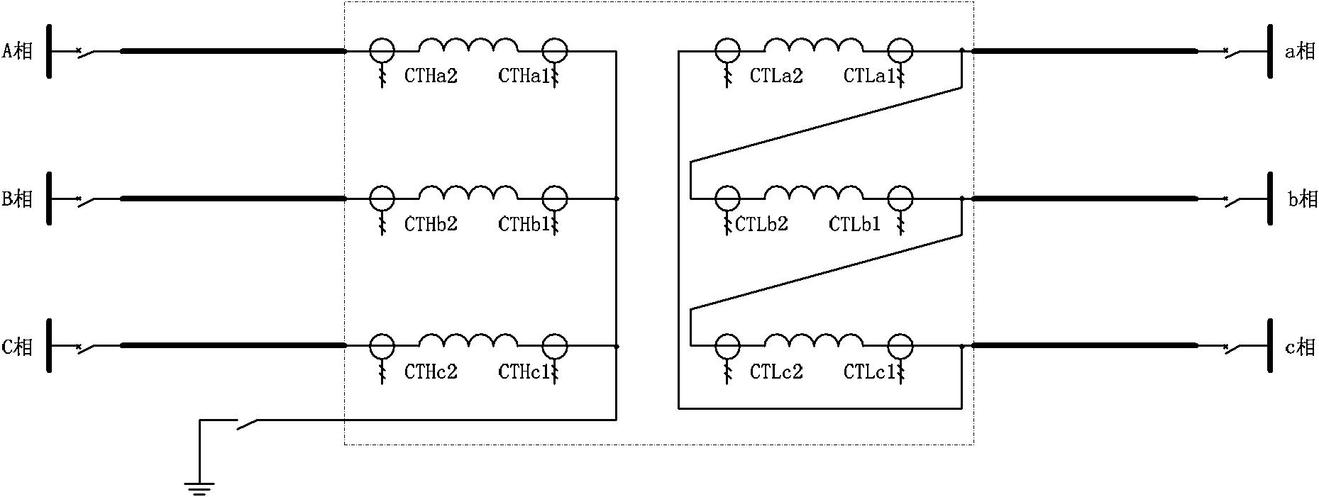
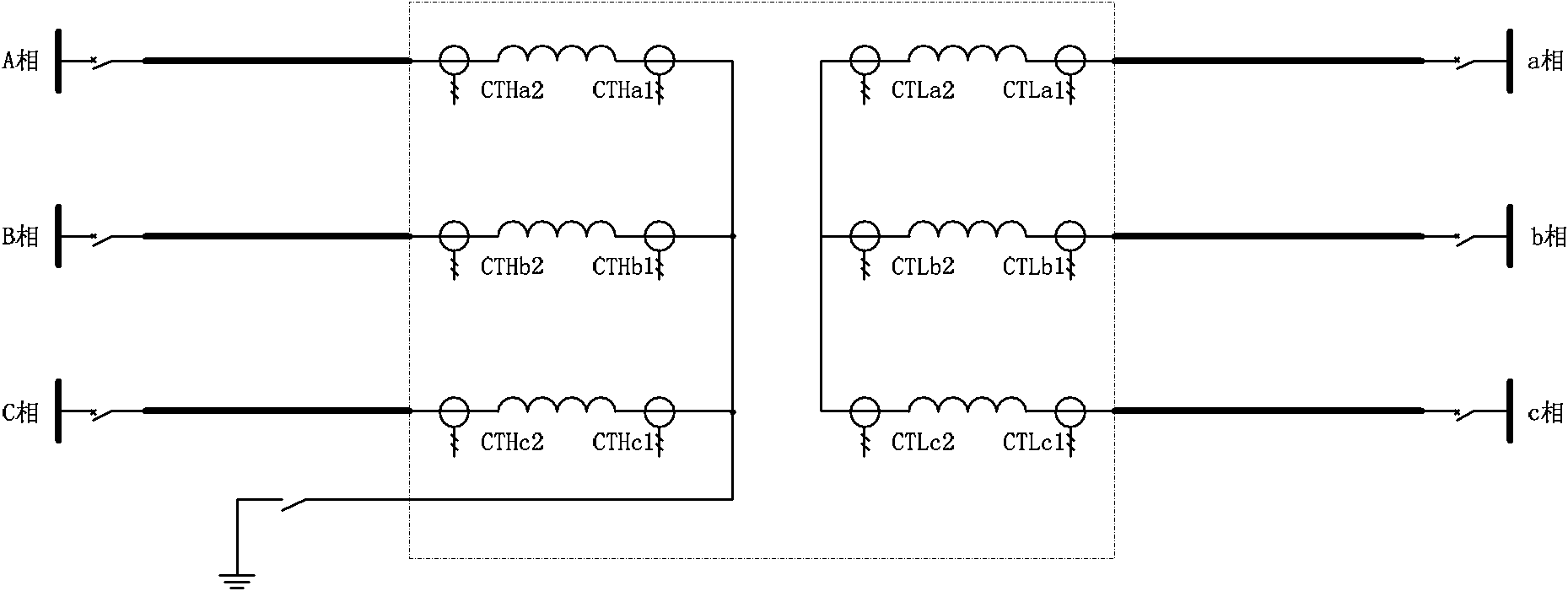
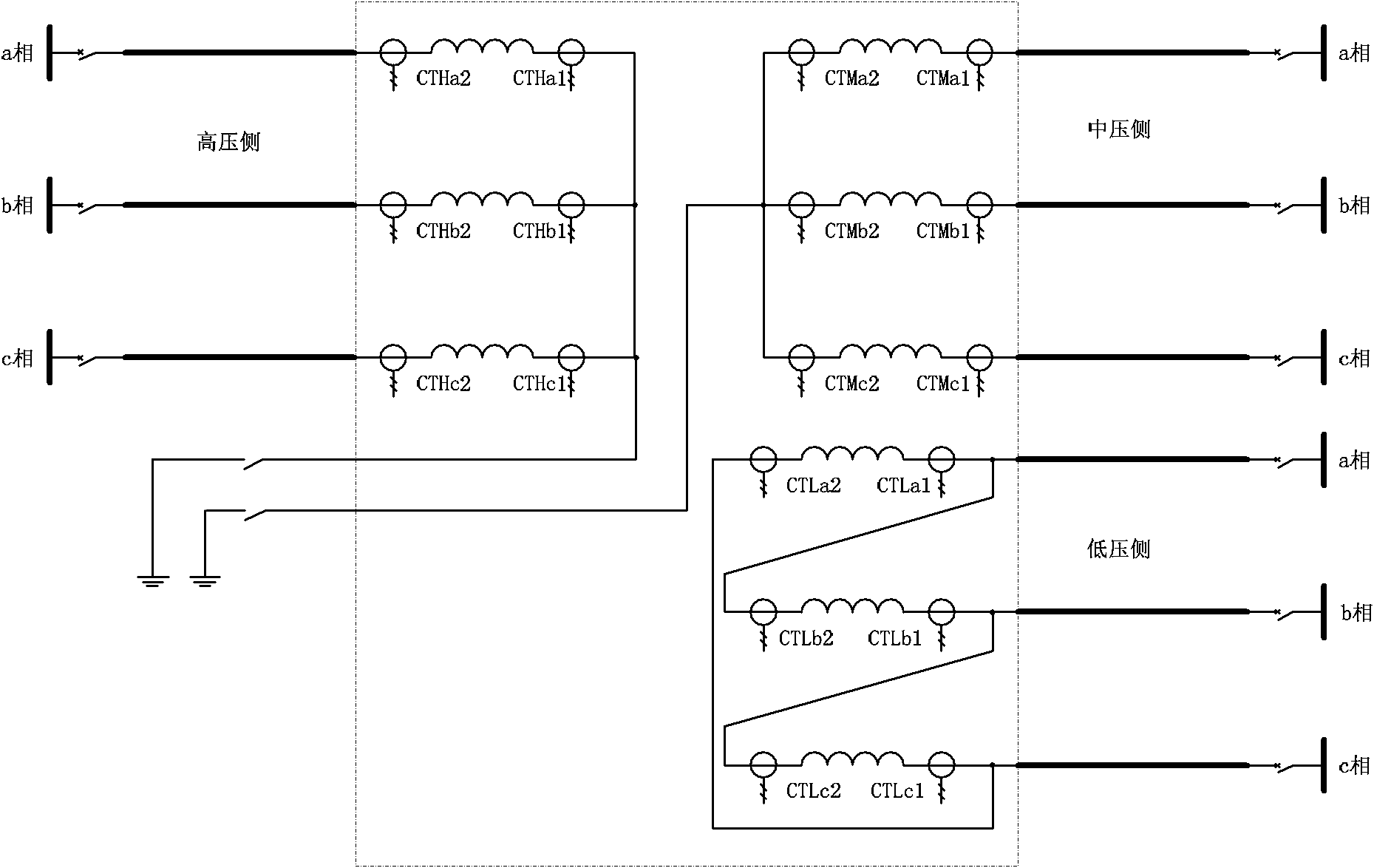
[0048] The built-in winding transformer current differential protection method for three-phase transformers is: based on Kirchhoff's current law, electromagnetic or electronic, photoelectric current transformers are installed inside double-winding or three-winding and other multi-winding transformers The two ends of each phase winding form a differential protection based on the current measured at the two ends of each winding, and act in response to the difference between the inflow current and the outflow current of each winding. It can not only correctly distinguish the internal faults of the winding, but also does not need to cooperate with ...


PUM


Abstract

The invention provides a current differential protection method for a built-in winding mutual inductor of a three-phase transformer. Current mutual inductors are installed at the two ends of each phase winding of the inner part of a duplex winding, three-winding or other multi-winding transformer to form current differential protection based on measuring current of two end heads of each winding. The data collected by each current mutual inductor is processed, the difference of the measuring current of two end heads of each winding forms differential current, and 0.05-0.2 time of rated current of the side transformer is used as the action threshold value of the differential current. The differential current is compared with a differential protection action current setting value. When the differential current is larger than the setting value, the winding differential protection acts according to the setting action time, and meanwhile a breaker of each side of the transformer is disconnected to eliminate winding faults. The current differential protection method is not influenced by inrush current, can effectively increase the sensitivity and rapidity of inner fault protection action of the transformer, does not delay to eliminate various shorted faults of the transformer windings, and obviously increases the correct action rate of transformer protection.

Description

technical field [0001] The invention relates to a current differential protection method for a built-in winding transformer of a three-phase transformer. It belongs to the technical field of power main equipment protection. technical background [0002] As the main electrical equipment widely used in the power system, the power transformer's safe operation is a necessary condition for the reliable operation of the power system. In the prior art, three-phase transformers generally adopt dual configurations of longitudinal differential protection and gas protection as the main protection. Among them, the current transformer of the traditional differential protection is installed on the lead-out line between the transformer and the circuit breaker, which can reflect the phase-to-phase short-circuit fault of the transformer winding and the lead-out line, as well as the fault of the grid-side winding and lead-out line of the neutral point directly grounded system. Short circuit...

Claims


Application Information

Patent Timeline
Patent Type & Authority Applications(China)
IPC IPC(8): H02H7/045
Inventor 熊小伏陈星田王建王嫱
Owner 重庆峰极智能科技研究院有限公司
Why Eureka
Try Eureka