Detoxifying method of chlorine trifluoride

A chlorine trifluoride, fluorine gas technology, applied in chemical instruments and methods, separation methods, gas treatment and other directions, can solve the problems of difficult separation or concentration, difficult to remove, etc.

Active Publication Date: 2011-08-03
CENT GLASS CO LTD
View PDF5 Cites 4 Cited by
  • Summary
  • Abstract
  • Description
  • Claims
  • Application Information

AI Technical Summary

Problems solved by technology

Furthermore, in terms of physical properties and ClO 3 F Similar gases contain low concentrations of ClO 3 In the cas

Method used


Image

  • Detoxifying method of chlorine trifluoride
  • Detoxifying method of chlorine trifluoride

Examples


Embodiment 1

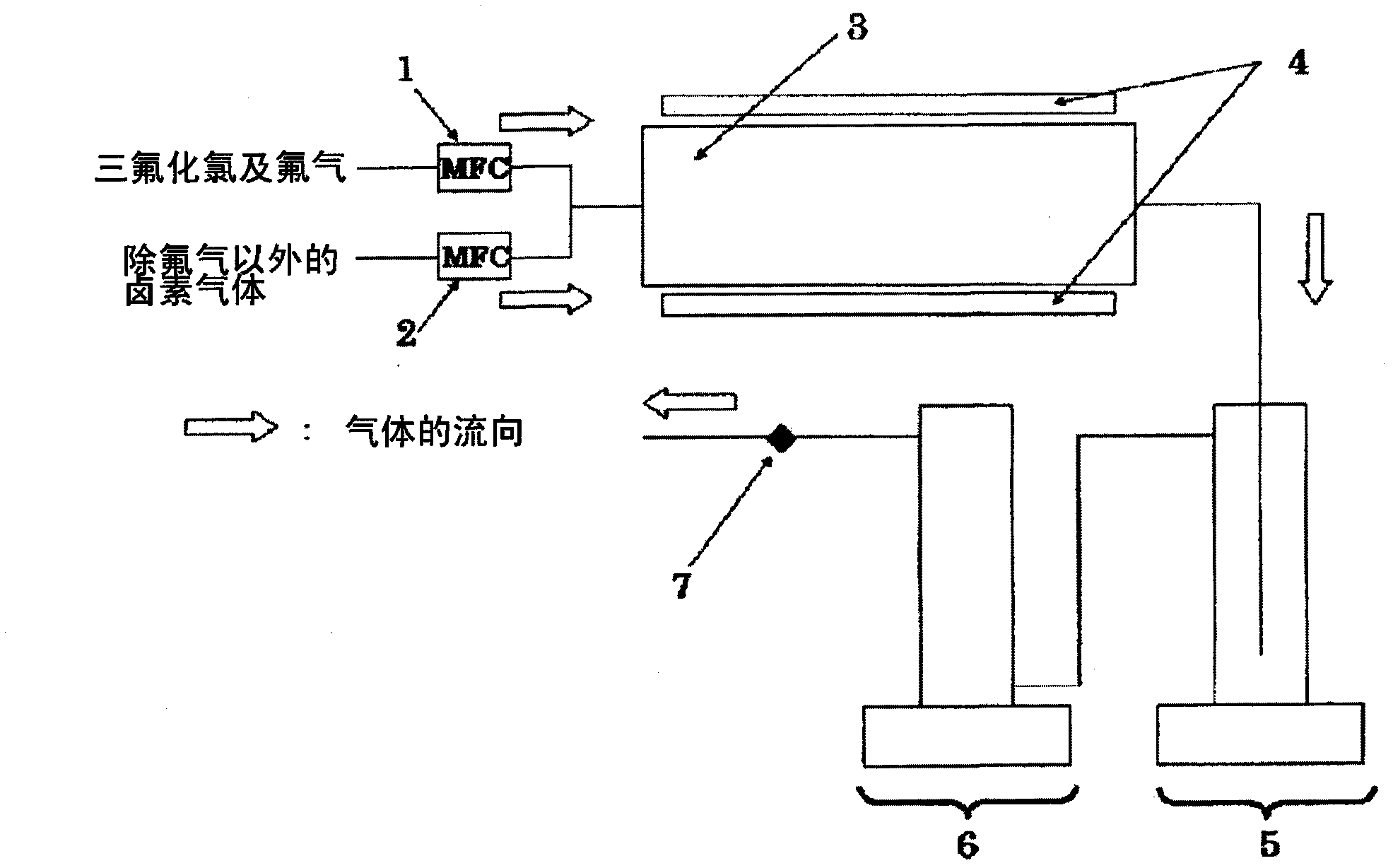
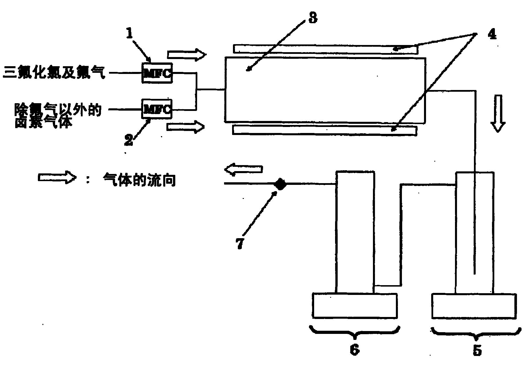
[0047] The temperature of the outer wall of the nickel cylindrical reactor 3 with an inner diameter of 30 mm and a length of 600 mm is set to 350° C., and a mass flow controller 1 is used to introduce 2.8 mol% of Fluorine and 3.5mol% ClF 3 and use mass flow controller 2 to introduce 3.4mol% chlorine gas at a flow rate of 10ml / min, make it react for 30 seconds, and then pass through the water scrubber (exhaust gas treatment device) connected to the rear stage 5 and the scrubber (exhaust gas treatment device) 6 of the alkaline solution whose KOH concentration is 0.1mol / l carry out detoxification treatment, then, the outlet gas that the scrubber circulates is sampled, using FT-IR (manufactured by Otsuka Electronics Co., Ltd. IG-1000) to ClO3 The concentration of F was analyzed and the result was 180 volppm.

Embodiment 2

[0051] The temperature of the outer wall of the nickel cylindrical reactor 3 with an inner diameter of 12.4mm and a length of 1000mm is set to 350°C, and a mass flow controller 1 is used to introduce 5.0mol% Fluorine gas and 3.0mol% ClF 3 and use the mass flow controller 2 to introduce 6.0mol% chlorine to it at a flow rate of 44ml / min, make it react for 30 seconds, then pass through the water scrubber (exhaust gas treatment device) connected to the rear stage 5 and the scrubber (exhaust gas treatment device) 6 of the alkaline solution whose KOH concentration is 0.1mol / l carry out detoxification treatment, then, the outlet gas that the scrubber circulates is sampled, using FT-IR (manufactured by Otsuka Electronics Co., Ltd. IG-1000) to ClO 3 The concentration of F was analyzed and the result was 4 volppm.

Embodiment 3

[0055] The temperature of the outer wall of the nickel cylindrical reactor 3 with an inner diameter of 30 mm and a length of 600 mm is set to 370° C., and a mass flow controller 1 is used to introduce 2.8 mol% of Fluorine and 3.5mol% ClF 3 and use mass flow controller 2 to introduce 3.4mol% chlorine gas at a flow rate of 10ml / min, make it react for 30 seconds, and then pass through the water scrubber (exhaust gas treatment device) connected to the rear stage 5 and the scrubber (exhaust gas treatment device) 6 of the alkaline solution whose KOH concentration is 0.1mol / l carry out detoxification treatment, then, the outlet gas that the scrubber circulates is sampled, using FT-IR (manufactured by Otsuka Electronics Co., Ltd. IG-1000) to ClO 3 The concentration of F was analyzed and the result was 160 volppm.


PUM


Abstract

The invention discloses a detoxifying method which is a method for eliminating unwanted substances from a mixed gas composed of at least chlorine trifluoride and fluorine with a wet scrubber. As a pre-treatment step for the elimination of unwanted substances with the wet scrubber, the method involves a step of adding a halogen gas (X2) (wherein X represents Cl, Br or I) to the mixed gas to cause the reaction between fluorine contained in the mixed gas with the halogen gas (X2) (wherein X represents Cl, Br or I), thereby reducing the content of fluorine in the mixed gas and preventing the generation of perchloryl fluoride (ClO3F) in the wet scrubber.

Description

technical field [0001] The invention relates to a method for removing harm from a mixed gas containing chlorine trifluoride and fluorine. Background technique [0002] As we all know, as shown in the following reaction formula 1, chlorine trifluoride (ClF 3 ) can be synthesized by the direct reaction of chlorine gas and fluorine gas (non-patent literature 1, 2). [0003] [chemical formula 1] [0004] Cl 2 +3F 2 →2ClF 3 [0005] in the usual ClF 3 In the manufacturing process of , the ClF generated in the reactor 3 By cooling the trap, only the target product is selectively trapped. [0006] Typically, unreacted F is contained in the gas passing through the cooled trap 2 gas, untrapped ClF 3 , Therefore, detoxification treatment can be carried out by using a wet scrubber (exhaust gas treatment device) using water or alkaline solution. [0007] However, in the case of ClF by using a wet scrubber using water 3 and F 2 When the mixed gas is used for detoxification t...

Claims


Application Information

Patent Timeline
IPC IPC(8): B01D53/68B01D53/77
CPCB01D53/68B01D53/76B01D2251/10B01D53/1406B01D2257/204B01D2251/108B01D2257/2027B01D53/75B01D53/77
Inventor 梅崎智典毛利勇
Owner CENT GLASS CO LTD
Why Eureka
Try Eureka