Capping machine
A capping machine and capping technology, applied to bottle/container caps, capping containers tightly with caps, filling bottles, etc., can solve problems such as complex structure, increased cost and difficulty in regulation, and achieve simple and compact structure and convenient regulation , to ensure the effect of air cleanliness
- Summary
- Abstract
- Description
- Claims
- Application Information
AI Technical Summary
Problems solved by technology
Method used
Image


Examples
Embodiment Construction
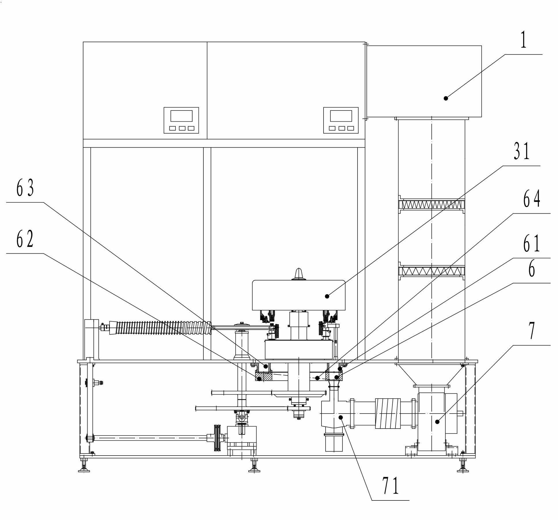
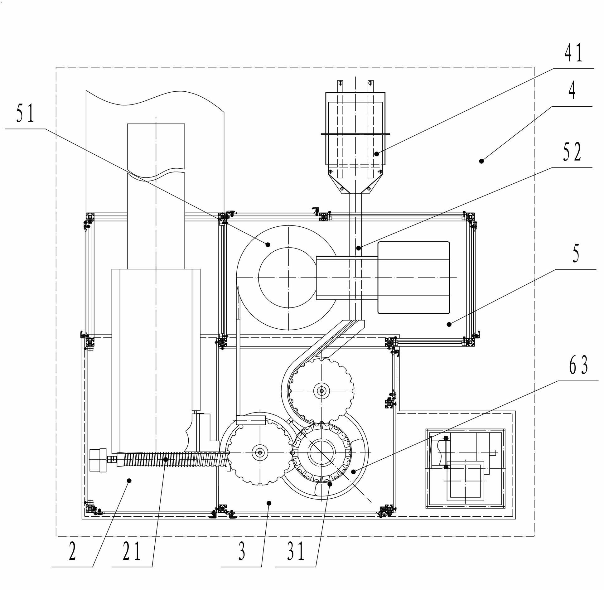
[0016] figure 1 with figure 2 A kind of capping machine embodiment of the present invention is shown, and this capping machine comprises laminar flow hood 1, is provided with below laminar flow hood 1 and is positioned at B level laminar flow into the cabin 2, is positioned at the capping of A level laminar flow. The cabin 3 and the bottle outlet cabin 4 located under the C-level laminar flow, the bottle outlet of the bottle inlet cabin 2 is connected with the bottle inlet of the capping cabin 3, and there is a For the safety cabin 5 under flow or Class B laminar flow, the bottle outlet of the capping cabin 3 is connected to the bottle inlet of the safety cabin 5, and the bottle outlet of the safety cabin 5 is connected to the bottle inlet of the bottle outlet cabin 4. This arrangement The structure isolates the bottle outlet chamber 4 and the capping chamber 3, avoids the gas exchange and pollutes the capping chamber 3, ensures the cleanliness of the air in the capping cham...
PUM
 Abstract
Description
Claims
Application Information
 - R&D
- Intellectual Property
- Life Sciences
- Materials
- Tech Scout
- Unparalleled Data Quality
- Higher Quality Content
- 60% Fewer Hallucinations
Browse by: Latest US Patents, China's latest patents, Technical Efficacy Thesaurus, Application Domain, Technology Topic, Popular Technical Reports.
© 2025 PatSnap. All rights reserved.Legal|Privacy policy|Modern Slavery Act Transparency Statement|Sitemap|About US| Contact US: help@patsnap.com