
Phase change cold accumulating independent dehumidification floor cold supply system

A phase change cold storage and cooling system technology, applied in the field of floor cooling system, can solve the problems of inability to solve the problem of energy consumption of the floor radiant cooling system, poor ability to utilize the location heat source, and inability to separate heat and humidity, so as to eliminate indoor humidity. The effect of low load, low electricity price, and increased evaporation temperature

Inactive Publication Date: 2011-08-10
SHANGHAI JIAO TONG UNIV
View PDF7 Cites 0 Cited by
  • Summary
  • Abstract
  • Description
  • Claims
  • Application Information

AI Technical Summary

Problems solved by technology

However, there are still many problems in the current floor cooling system, mainly focused on: 1. Energy consumption issues: At present, the floor cooling system and the fresh air system mostly use air as the cold and heat source, and the same temperature is produced by the same refrigeration unit. Low-temperature chilled water for radiant cooling and fresh air dehumidification makes the energy efficiency of the unit relatively low, the ability to utilize local heat sources is poor, the energy utilization rate is low, and the operating cost is high
2. The reheating problem of fresh air: the temperature of the fresh air after dehumidification is too low, and it will cause discomfort to the human body if it is directly sent into the room. At present, a heater is usually used to reheat the fresh air at the cost of consuming excess power
However, this method cannot solve the energy consumption problem of the floor radiant cooling system, and still needs to dissipate excess energy to heat the supply air, and because the chilled water of the floor coil and the fan coil comes from the same compressor system, it still cannot transfer heat The wet treatment is completely separated, which cannot meet the needs of users for separate refrigeration or separate dehumidification

Method used


Image

  • Phase change cold accumulating independent dehumidification floor cold supply system
  • Phase change cold accumulating independent dehumidification floor cold supply system

Examples


Embodiment Construction

[0014] The embodiments of the present invention are described in detail below. This embodiment is implemented on the premise of the technical solution of the present invention, and detailed implementation methods and specific operating procedures are provided, but the protection scope of the present invention is not limited to the following implementation example.

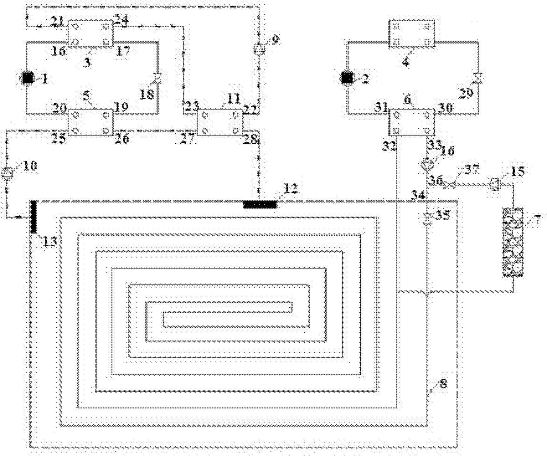
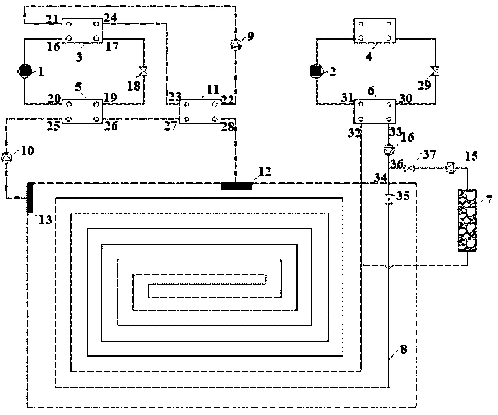
[0015] Such as figure 1As shown, the device in this embodiment includes: a first compressor 1, a second compressor 2, a first condenser 3, a second condenser 4, a first evaporator 5, a second evaporator 6, and a phase change cold storage device 7 , floor radiant coil 8, first fan 9, second fan 10, heat exchanger 11, diffuser 12, air outlet 13, first water pump 14 and second water pump 15. Wherein: the output end of the first compressor 1 is connected to the first input end 16 of the first condenser 3, the first output end 17 of the first condenser 3 is connected to the input end of the first throttle valve 18, and...


PUM


Abstract

The invention discloses a phase change cold accumulating independent dehumidification floor cold supply system in the technical field of building environments and equipment engineering. The system comprises two compressors, two condensers, two evaporators, a phase change cold accumulating device, a floor radiation coil pipe, two air blowers, a heat exchanger, an air supply diffuser and an exhaust port. Independent control of temperature and humidity of the cold supply system is realized, the operation is controllable and flexible, and the energy efficiency ratio of a refrigerating unit is improved; effective combination of a phase change cold accumulating technology and a floor radiation cold supply technology is realized, power supply tension is relieved, and the utilization efficiency of electrical energy is improved; reclamation of condensation heat is realized, thermal pollution is relieved, consumption of the electrical energy is reduced, and the working conditions of the condensers are improved; and the purposes of energy conservation and environmental friendliness are finally implemented.

Description

technical field [0001] The invention relates to a cooling system in the technical field of building environment and equipment engineering, in particular to a phase-change cold storage type floor cooling system with independent dehumidification. Background technique [0002] Floor radiant cooling technology is gradually developed on the basis of floor heating technology, and its feasibility has been increasingly certified. It has the advantages of energy saving, strong comfort, shifting peak power consumption, convenient single household control and heat metering, etc. However, there are still many problems in the current floor cooling system, mainly focused on: 1. Energy consumption issues: At present, the floor cooling system and the fresh air system mostly use air as the cold and heat source, and the same temperature is produced by the same refrigeration unit. Low-temperature chilled water is used for radiant cooling and fresh air dehumidification, which makes the energy ...

Claims


Application Information

Patent Timeline
Patent Type & Authority Applications(China)
IPC IPC(8): F24F5/00F24F12/00
CPCY02E60/147Y02E60/14
Inventor 翟晓强王晓霖杨燕李悦裴海涛
Owner SHANGHAI JIAO TONG UNIV
Learn More