Manufacture technique for plugging sheet of attaching plug

A manufacturing process and power plug technology, applied in metal processing equipment and other directions, can solve the problems that the forming substrate cannot be fully utilized, the boundary cannot achieve the desired effect, and the production efficiency is reduced, and achieves the ideal product boundary and utilization rate. High, reasonable process arrangement effect

Inactive Publication Date: 2011-08-17
苏辉
View PDF4 Cites 4 Cited by
  • Summary
  • Abstract
  • Description
  • Claims
  • Application Information

AI Technical Summary

Problems solved by technology

[0003] Because the inserts for the power plugs formed by stamping are arranged side by side, and the width of the left and right crimping cards 71, 72 is wider than the inserts for the power plugs, this method of separation cuts off a lot of metal materials, so that the forming base material cannot be fully formed. Utilization will cause waste of materials, and the process of removing materials at the same time will reduce the efficiency of production. Stamping multiple plugs for power plugs at one time will also cause the forming boundary to fail to achieve the desired effect. In view of the above problems, it is necessary to make some improvements.

Method used


Image

  • Manufacture technique for plugging sheet of attaching plug
  • Manufacture technique for plugging sheet of attaching plug
  • Manufacture technique for plugging sheet of attaching plug

Examples


Embodiment Construction

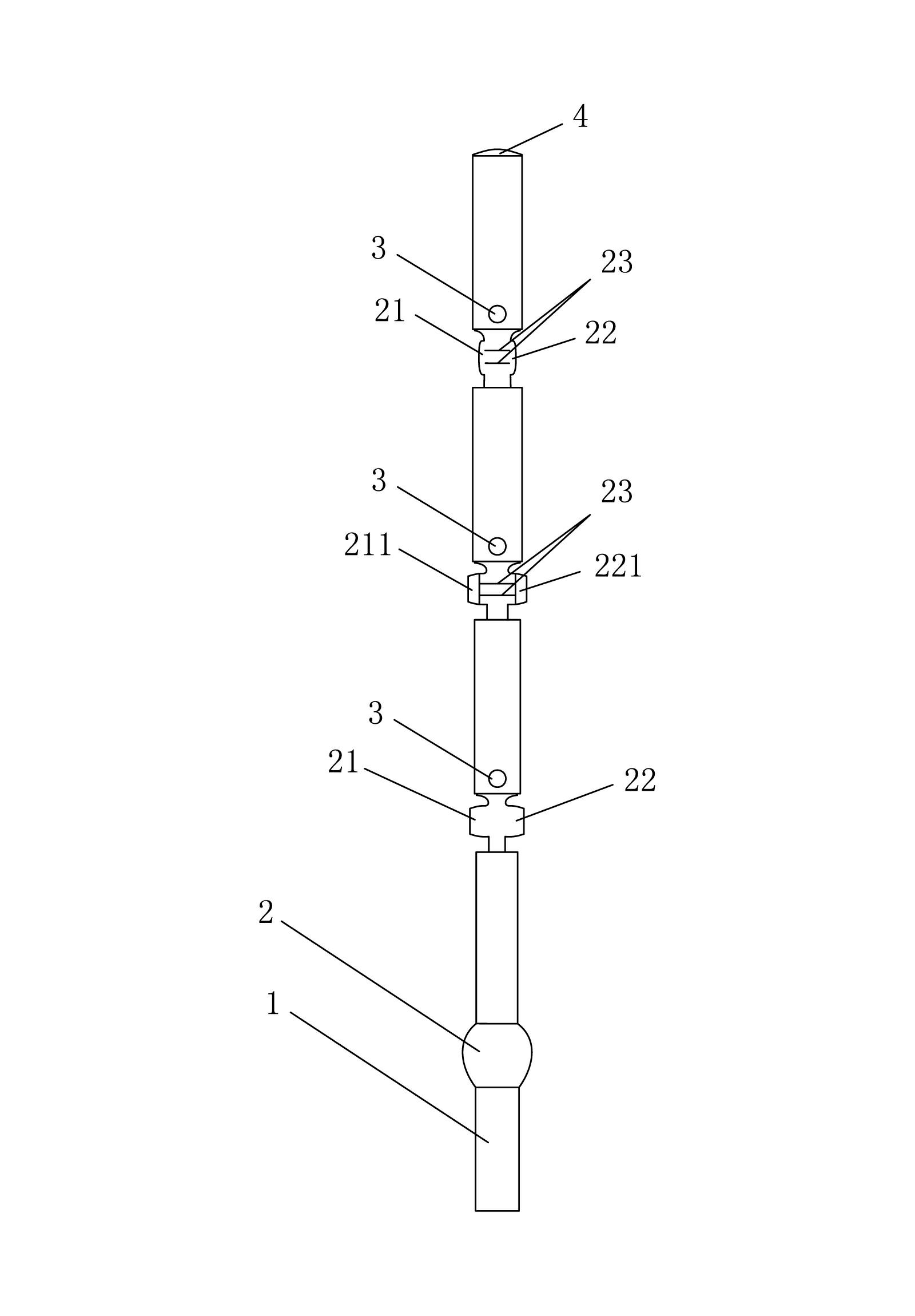
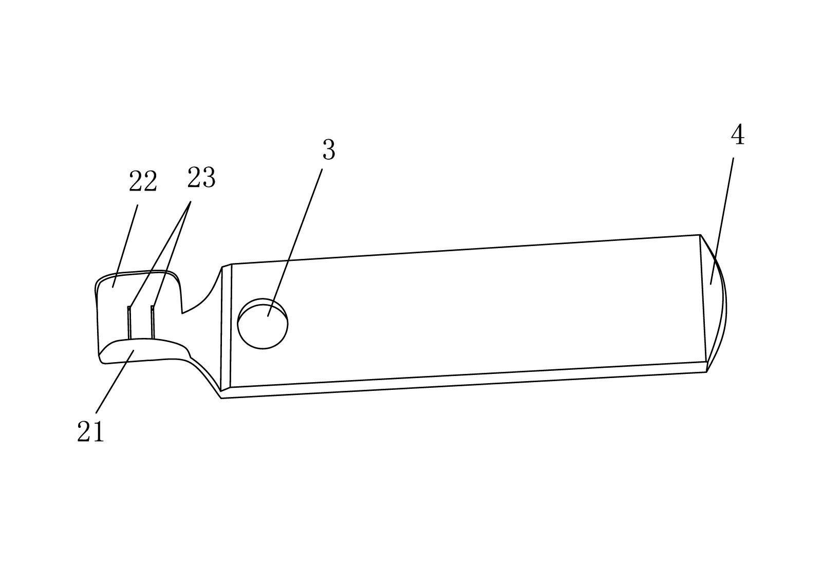
[0018] refer to figure 1 , figure 2 , a manufacturing process of an insert for a power plug, the process steps are as follows:

[0019] (1) Forming of long copper strips: according to the width and thickness of the finished inserts, long copper strips 1 are produced;

[0020] (2) Feed the long copper bar 1 into the mold to stamp and flatten the riveting groove position 2 of the insert. The punching thickness is 1.2 to 1.3 times the thickness of the riveting groove position of the finished insert, and the punching length is the finished insert. 1.5 to 2 times the length of the riveting groove;

[0021] (3) The long copper bar 1 produced in step 2 is stamped and shaped for the riveting groove position 2, so as to produce the left and right crimping cards 21 and 22 that conform to the size and thickness of the finished insert, and at the same time carry out Stamping of insert positioning hole 3;

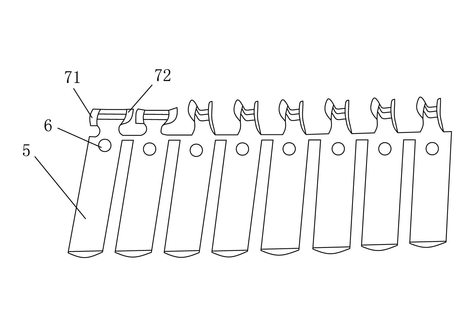
[0022] (4) For the long copper bar 1 produced in step 3), carry out the third...


PUM


Abstract

The invention discloses a manufacture technique for a plugging sheet of an attaching plug, which comprises the steps as follows: long copper strips are formed; riveting trough positions are punched and flattened; left and right grooving cards and plugging sheet locating holes are punched and formed; anti-skid troughs are punched on the middle positions of the riveting troughs; meanwhile, inclinations are punched on the left and right grooving cards; then the left and right grooving cards are bent; meanwhile, forming treatment is implemented on the top ends of the long copper strips; then single plugging sheet is cut off; and finally the upper sides and the lower sides of the top end of the long copper strips are obliquely punched. In the technical method, metal materials do not need to be cut off, the utilization rate on the base materials for forming is high, and material wastes are reduced; meanwhile, the manufacture technique has more reasonable technique arrangement, and improves the production efficiency; moreover, the boundary effects of the products manufactured through the manufacture technique are ideal compared with the boundary effects of the products obtained through a commonly-used manufacture technique which manufactures a plurality of plugging sheets of an attaching plug in parallel.

Description

technical field [0001] The invention relates to a manufacturing process of an insert, in particular to a manufacturing process of an insert for a power plug. Background technique [0002] refer to image 3 , the production process of the inserts for power plugs currently on the market is: 1. Use copper materials to press into a metal plate 5 according to the thickness of the finished power plug. The width of the metal plate 5 is the same as the length of the finished power plug. The cutting machine slices off a certain amount of material according to the thickness of the finished product at the position of the riveting groove of the power plug; 3. According to the size of the finished product of the power plug, punch out multiple power plug blanks side by side on the metal plate 5, and the middle parts of the power plug blanks are connected. ; 4. Forming the top of the power plug blank and punching the positioning hole 6; 5. Bending the left and right crimping cards 71, 72; ...

Claims


Application Information

Patent Timeline
Patent Type & Authority Applications(China)
IPC IPC(8): B21D53/00
Inventor 苏辉
Owner 苏辉
Why Eureka
Try Eureka